Nikola Tesla's Wireless Transmitters
Alternator, Frequency Stability, Resonance Geometry, Waveguides, Wireless Energy Transmission, Communications Links
Understanding the Tesla system of transmission of electrical energy, first means understanding the demonstrated physics of Tesla's first alternating current motor/generator patents.
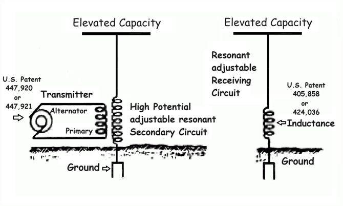
US Patents: 447,920 - 447,921 - 405,858 - 424,036
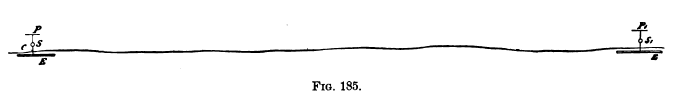
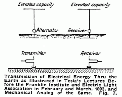
Fig 185 above comes from Tesla's lecture before the Franklin Institute, February 1893. Fig 7 below it comes from an article Tesla wrote for Electrical Experimenter, May 1919 and shows the mechanical analog of Figure 185: a tuning fork power supply or mechanical "modulator", in the place of Tesla's patented high-frequency alternator 447,920. The principal of operation throughout is the same as for the tin-can telephone.
Also See: The Problem of Increasing Human Energy - Diagram c
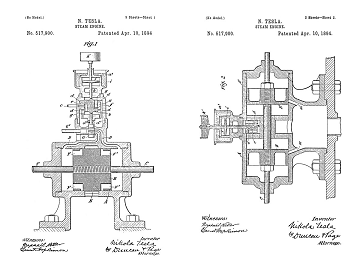
447,920
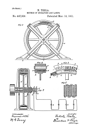
Method of Operating Arc Lamps - Oct 1, 1890
Using a two-phase isochronous generator to lock in the field magnet frequency of a synchronous motor: the motor armature turns with a frequency locked output: the rotational speed of the motor shaft does not change. By directly coupling the output shaft of a freqency locked synchronous motor to the drive shaft of the alternator 447,920: a frequency locked sine wave alternating current output is produced. This also applies to 447,921.
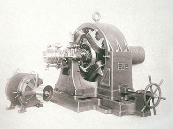
Photos of actual machines show field magnet electrical terminals mounted on the base of the alternator frame (See the photo in 447,920), or terminals mounted on the top portion of the ring shaped field. These field magnets are power hungry, and they can get pretty hot. Tesla shows the machine in patent as self-excited, the field magnet winding is a closed coil of wire. In order to start this alternator in self-excited mode, you first have to flash the armature output terminals with a DC power supply while it is spinning: this surge of electrical current produces a magnetic field which starts current flowing in the closed coil, creating the field magnetism. As long as power is taken off the armature slip rings, the field magnet remains self-excited.
But the way a machine is shown and operated in patent, does not at all cover cases of R&D applications. In the laboratory, and in the lecture demonstrations, this type equipment was shown, and photographed, with multiple field magnet terminals. Tesla used auxillary power supplies or "exciters" to energize these field coils, up to 550 volts DC was routinely applied for short periods, and the connections are made to the terminals shown in photos, but not shown in patent.
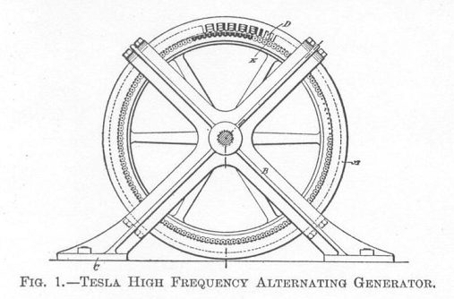
Tesla had demonstrated his technique of using an alternating current to create a rotating magnetic field in a generator, that allowed the output frequency of the generator to greatly exceed the shaft speed of the armature. Tesla documented this technique in patent, and in demonstrations. These experiments allowed Tesla to reach radio frequencies using iron core generators: but the frequency stability was so poor that these power supples were only really suitable for lighting experiments. As frequencies reach into the radio range, the reliability of coherer receiver technology declines, rotational receivers become impractical, and wireless motor technology is impossible. Coherers gradually become less sensitive at higher frequencies, and are pretty much insensitive above 100 kilohertz, they work best in the VLF range between 3 and 30 kilohertz. In order to operate motors effectively in this system the fundmental frequency needs to be below 10 kiloherz in order for the energy to interact with the iron motor cores.
Tesla repeatedly went on, and on, that his wireless work was being both misinterpreted, and misapplied, by others. His first complaint was about Marconi who was granted a patent for radio, but never actually used the patented technology to send or receive a signal. Marconi formed an investment group and they tried to leverage the patent into an international monopoly in wireless technology. Tesla stated on record that when actually transmitting and receiving, Marconi was using at least a half-dozen Tesla patents. The second complaint was the race to higher frequencies and radiation physics. Tesla's argument is quite valid. He stated that at higher frequencies the energy radiated off into space and only a very tiny percentage could be recovered, and the precentage recovered required expensive and technologically challenging amplification to be useable. The alternative he offered was to keep the frequencies low, low enough to severely retard radiation out into space, and to conduct this energy using naturally formed, insulated, wave guides: first along the ground, and then at high power levels combine the ground wave with a direct conductive connection at about 42,000 feet. Doing this Tesla argued would allow significant recovery of the transmitter energy possible, even allowing the operation of lamps and motors by the receiver.
The generation of line frequencies that were greatly in excess of the armature shaft speed, multiplied problems with frequency instability and drift. Using an isochronous generator to produce a frequency locked rotating magnetic field in a synchronous motor that is directly shaft-coupled to drive the Tesla alternator 447,920 keeps the alternator signal frequency locked to the pulse timing produced by the isochronous generator. This line of research results in much lower than "true" radio frequencies [Tesla frequencies stick to conductors, like the earth], below 33 kHz in fact using 447,921, but Tesla was able to obtain the frequency stability required for the practical wireless transmission of intelligence: wireless communications. His system depends on using the Earth's ground as a conductive waveguide, and operating at frequencies that radiate easily defeats the purpose. To operate motors wirelessly, the frequencies need to be low enough to couple to the iron motor cores. The alternator set up and operated in this mode has a perfectly timed sine wave output without the lagging, overspeed, and drifting about in oscillations between too fast, and too slow, which is normal in this type of rotational, belt-driven, iron shaft technology.
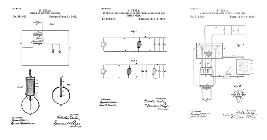
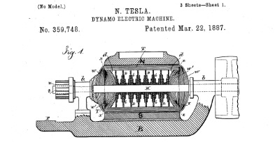
406,968
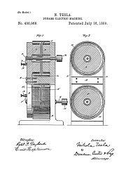
Dynamo-Electric Machine - March 23, 1889
Prior discussions on this patented dynamo are located Here & Here.
US Patent 406,968 was developed and patented as a laboratory research instrument and practical DC power supply for the lab. Tesla documented the measured electromagnetic geometries in an article published in Electrical Engineer, Sept 2, 1891.
Tesla patented this as a DC generator, or dynamo, and advises a self-excited configuration in patent, using closed coils. In practice, there were holes in the casting and the coil ends for the field magnets were led out to terminals on the dynamo base. Using these terminals to make connections the field magnets could be self-excited (shorted or "closed coils"); excited with DC current from a battery or other DC power supply; or excited with an alternating current from a generator: both pulse wave, and fairly clean sine waves up to 30,000 Hertz, or cycles per second, were applied in this fashion. The machine could be taken apart and different field coils were experimented with: closed coils, closed loops of copper strap, and copper washers. When the field coils were externally excited with current between 2000 and 20,000 Hertz, rotation was produced in the conductive disc: so the dynamo also operates as a motor when the field is driven with alternating currents: shown in diagram as Figure 182 in Tesla's lecture before the Franklin Institute in 1893.
Tesla repeatedly states that he measured a slowing of time in iron cores using this equipment:
"I had discovered, however, that rotation is produced by means of a single coil and core; my explanation of the phenomenon, and leading thought in trying the experiment, being that there must be a true time lag in the magnetization of the core. I remember the pleasure I had when, in the writings of Professor Ayrton, which came later to my hand, I found the idea of the time lag advocated. Whether there is a true time lag, whether the retardation is due to eddy currents circulating in minute paths, must remain an open question, but the fact is that a coil wound upon an iron core and traversed by an alternating current creates a moving field of force, capable of setting an armature in rotation." - Tesla lecture before the IEE, 1892
Also See: "Magnetic Lag" Motor - 424,036
"In order to operate such a motor effectively on the plan indicated, the frequencies should not be too high, not more than four or five thousand, though the rotation is produced even with ten thousand per second, or more." - N. Tesla, Franklin Institute, 1893.
The conductive discs are motor armature "receivers", or generators, depending on how they are configured and powered. Measurements determined the spiral EMHD flow geometry across the surface of the disc and the resulting magnetic/current lag functions. The motor armature core geometry that Tesla documented in US Patent 405,858... A high-energy angular-displacement motor was derived from the voltage, current, and magnetic lag studies performed on 406,968. These disc and spiral core geometries are electromagnetically resonant when energy is properly applied to them. Resonance was patented in:
512,340

Coil for Electromagnets - July 7, 1893
512,340 above is also directly derived from physical measurements and advanced research studies using the disc and core of 406,968.
When the coil in 512,340 is operating in resonance, multiple functions in the coil suddenly change. Tesla documents that every coil has a frequency such that the internal capacitance of the coil exactly cancels the inductive reactance at that frequency. Current then flows and sees no impedance, other than the measured ohmic resistance of the conductor, which can be made small. Tesla applies a winding technique to increase the internal capacitance, lowering the frequency, and allowing greater energy movement, or EMF, in the coil.
But other things are happening in the coil at resonance, there is also magnetic lag, even without the presence of iron. A high inductance in the copper winding mimics the behavior of an iron core, such that current lags behind the voltage by a measured angle of 90 degrees. This is the same angle of displacement Tesla has sought from the beginning of his motor/wireless development with the two-phase egg, with the phases 90 degrees apart, to his advanced motor armature patents with internal capacitor, and indeed, the "Coil for Electromagnets" is a type of high frequency motor armature, or a generator field. It is also a working particle model in Tesla's accelerator technology. It can act as a transmitter, or a receiver, and the coupling, or means of energy delivery, is a more efficient combination of inductive coupling and capacitive coupling, than can be obtained with a transmitter such as the iron core Egg, where the coupling is inductive only.
593,138
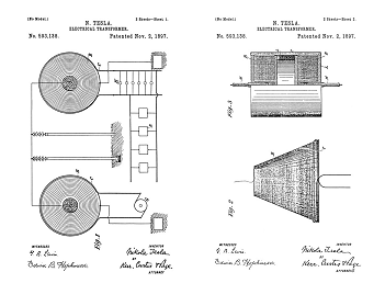
Electrical Transformer - Mar 20, 1897
The frequencies Tesla has discussed above for the operation of motors, between 4000-5000 Hertz or cycles per second, requires a wave guide to transmit effectively. This patent documents an iron core audio frequency transformer. The wave guide can transmit either a pure sine wave, or isochronous pulsitory waves. The power supply can be a high-frequency iron core alternator designed to be frequency locked with a rotating magnetic field produced by isochronous electromagnetic generators.
It can also be pulsed with the timed discharges from a capacitor. Tesla patented circuits for this purpose detailed in the section on Electrical Isochronous Oscillators.
A close examination of the wiring diagram in 593,138 shows that on the transmitting side, the conductor is insulated from the iron core; but on the receiving side the core is shown hot, with a direct electrical connection to the high-energy transmission line. The receiver side can be configured exactly as shown, as a transformer, with a grounded terminal; or the receiver side can be the armature Tesla patented in 405,858, and operated with a single wire connection to the shaft, as shown in US Patent 406,968 using spring clips. In this configuration no ground connection is required because the armature in 405,858 converts the energy into a rotating magnetic field and generates a local EMHD manifold, similar to that produced by Tesla's Egg of Columbus, but instead of strictly inductive coupling, the armature of 405,858 contains open-ended conductive and capacitive functions: the EMHD manifold streams off the rim of armature in this configuration and can be used to power the "Magnetic Lag" Motor - 424,036 wirelessly.
When the natural frequency of the coil in the transmitting side of 593,138 is adjusted to be resonant at the frequency output by the power supply, and this is generally done at these frequencies with the addition of finely divided and insulated iron added to the core, and shown in patent; the output of the resonant transformation contains inherent rotational functions in the wave form, even when the power supply is isochronous reciprocating. The efficiency of resonant conversion, using isochronous pulses to create output energy containing rotational functions is very high, but obtaining a pure sine wave with this method is technologically challenging.
593,138 can also be tuned and operated as the power supply to drive the coils D D in 405,858 when operated as a single-wire motor. Most of the line energy is converted directly into rotation, and the surrounding environment suffices for a return. 405,858 is quite the motor. These circuits, the armature shown in 405,858 and wireless operation of the lag motor form the basis for current Lab-Tesla Research and Development.
This is the only place on the planet currently where this information is completely documented and properly explained. Years of proprietary research is being disclosed into the public domain, free of charge.
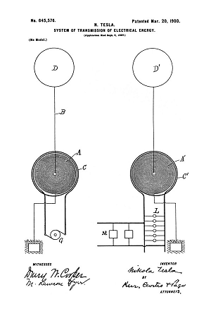
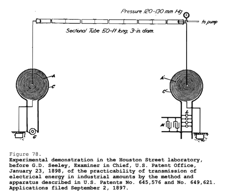
645,576
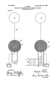
System of Transmission of Electrical Energy - Sept 2, 1897
649,621
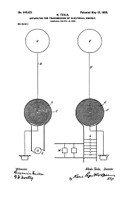
Apparatus for Transmission of Electrical Energy - Sept 2, 1897
645,576 and 649,621 are a patent split into a system and apparatus, the same technology is presented, but the patents are not identical and each contains proprietary information Tesla discloses.
Both of the above patents document iron core, low-frequency, wireless power transmitters. You have indications of direct iron core coupling in the fact that the power supply for the transmitters shown in diagram are iron shaft alternators with slip rings, essentially 447,920 is shown in patent as the power supply, but in addition to that, a close examination of the patent diagram at the highest available resolution shows an insulated dot in the center of the spiral winding. This tiny dot represents the small iron core, typically a thin walled steel pipe. In practice, and in patent, all of the wireless power transmitters have iron coupled in to the transmitter at some point in the circuit, and there may be iron located in several places in practice.
The above patents clearly state that with sufficient rarification of the atmosphere (42,000 feet), direct conductive coupling is established between the transmitter and the receiver air terminals. The ground terminals in these patents already serve as a direct conductive coupling between the transmitter and receiver elements. I have examined every aspect of this claim and it is very clear that these patents are valid when set up and operated as described. No Tesla transmitter patent comes close to operating frequencies in the radio range, and the Earth's surface is highly conductive when audio frequency currents are applied as directed in Tesla's patents. Note too that ground wave transmission modes do not depend on air terminals conducting energy to the receiver.
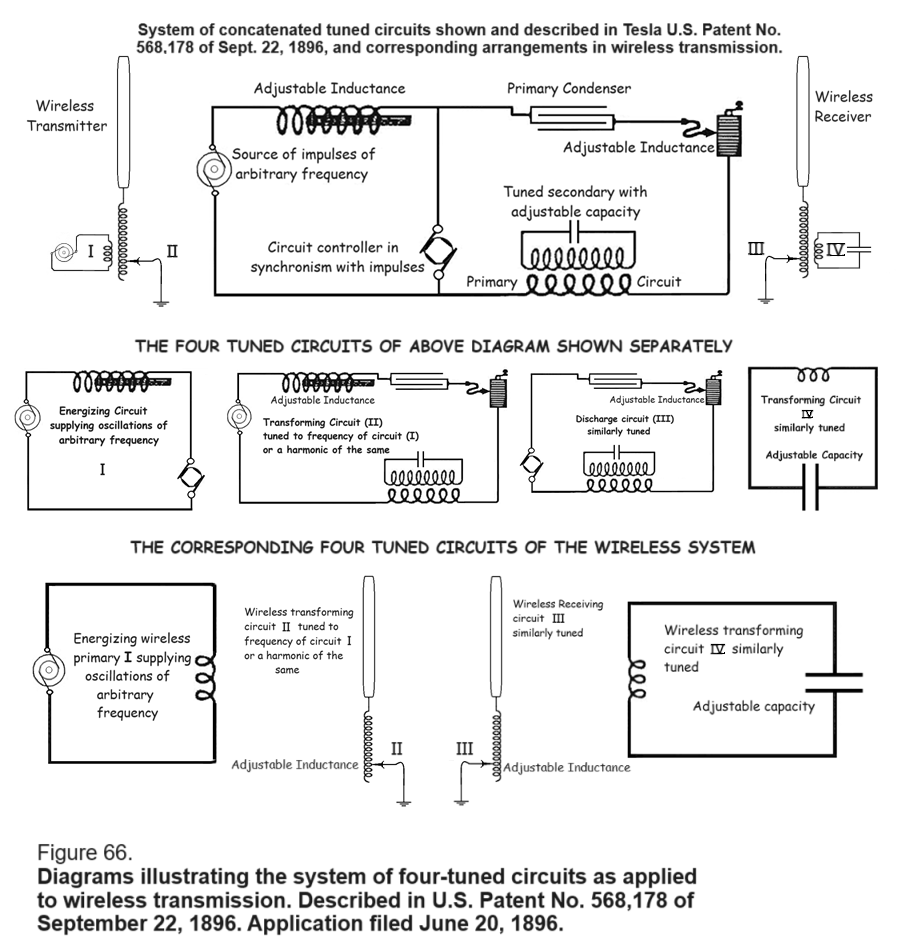
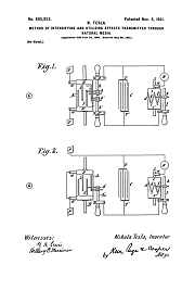
System of concatenated tuned circuits shown and described in Tesla U.S. Patent No. 568,178 of Sept. 22, 1896, and corresponding arrangements in wireless transmission.
The True Wireless, Electrical Experimenter, May, 1919.
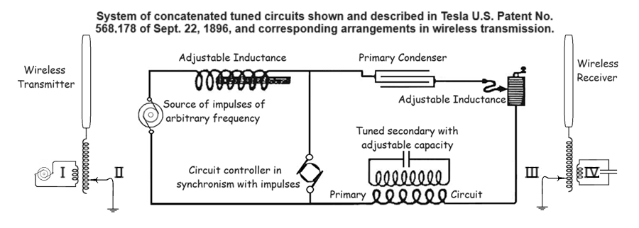
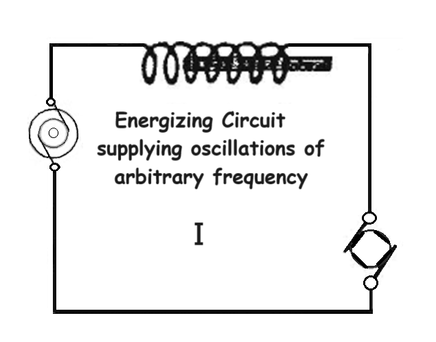
Here [Fig. 66] is something important, which I have tried to illustrate in a diagram. This diagram represents the system which I described in my patents of 1896, in which I showed four circuits in attunement, and I will endeavor to illustrate how these circuits are the exact equivalent of the wireless cicuits.
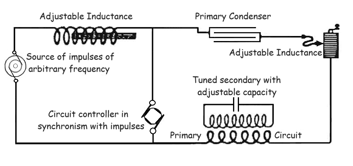
You see, here on the top I have titled, "System of concatenated tuned circuits shown and described in Tesla U.S. Patent No. 568,178 of Sept. 22, 1896, and corresponding arrangements in wireless transmission." - The first circuit which I have here is composed of a controller, a source of impulses of arbitrary frequency, and an adjustable inductance. I have drawn that circuit separately, and you see it here; that is my first circuit, "Energizing circuit supplying oscillations of arbitrary frequency I"
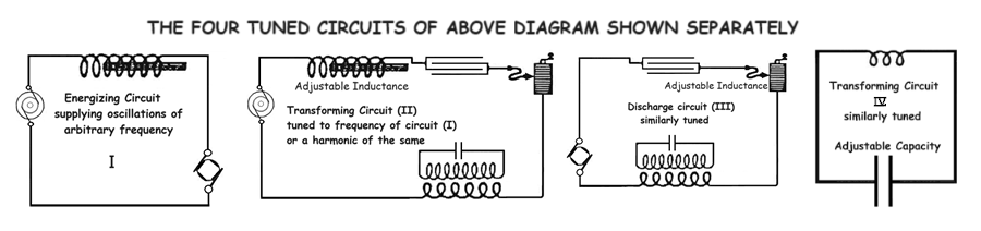
THE FOUR TUNED CIRCUITS IN THE ABOVE DIAGRAM SHOWN SEPARATELY
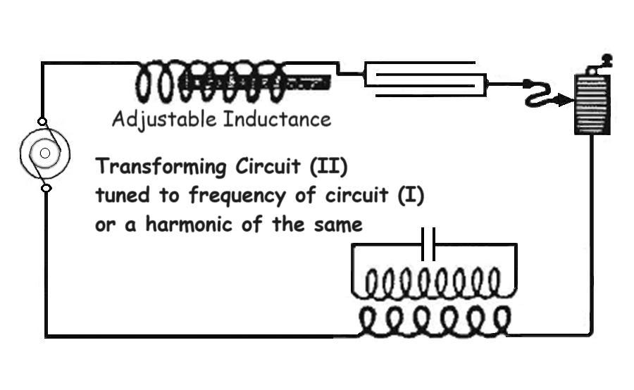
The second one is the circuit including the source, the adjustable inductance, this coil, and this primary. I have shown this circuit separately and marked it "Transforming circuit (II) tuned to the frequency of circuit (I), or a harmonic of the same."
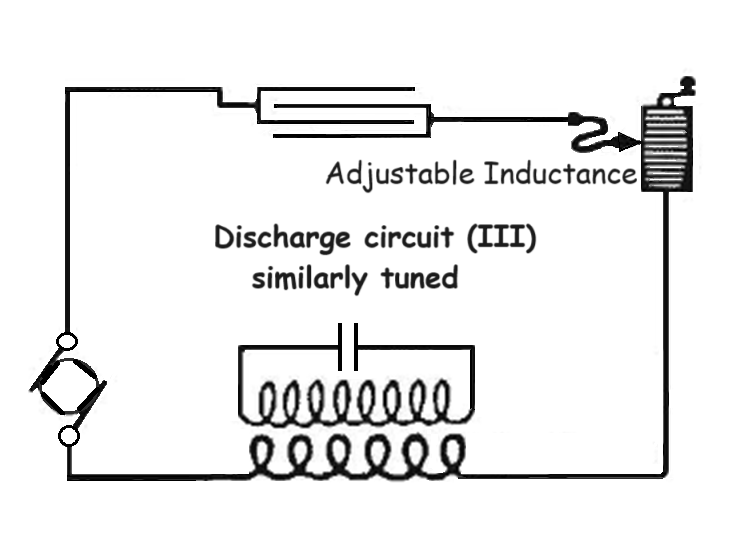
The third circuit is formed by the primary, the self-inductance, and the controller, and it is shown as "Discharge circuit (III) similarly tuned"
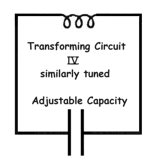
And then here is the fourth and last circuit with an adjustable capacity, shown as "Transforming circuit (IV) similarly tuned"
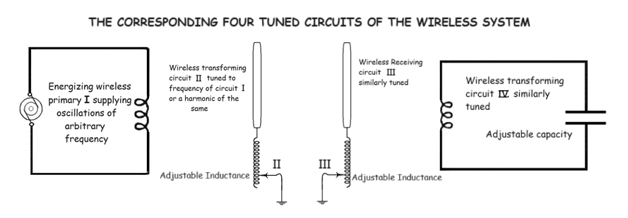
THE CORRESPONDING FOUR TUNED CIRCUITS OF THE WIRELESS SYSTEM
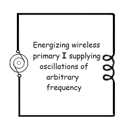
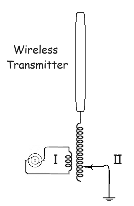
Now, if you look at wireless diagrams and bear in mind that I have, first of all, established the equivalency between two-wire and one-wire transmission, that I have then gone a step further and established the equivalency between the transmission through one wire and the transmission through the earth, which is wireless, then you will readily see that these wireless arrangements which are popular now, are merely an imitation of my arrangements, are in fact exactly the same. Here [Fig. 66 top left] is a wireless transmitter, comprising a primary circuit I, in which current impulses of arbitrary frequency are produced, corresponding to the circuit (I) in this figure.
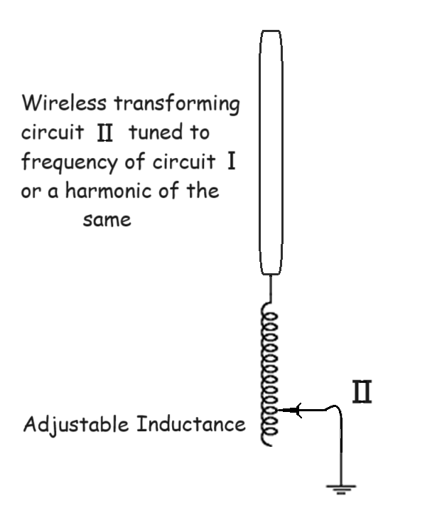
Here is the secondary tuned circuit connected to an antenna and to the ground, including an adjustable inductance, exactly as here; that is circuit II, which corresponds to this circuit (II) in my arrangement.
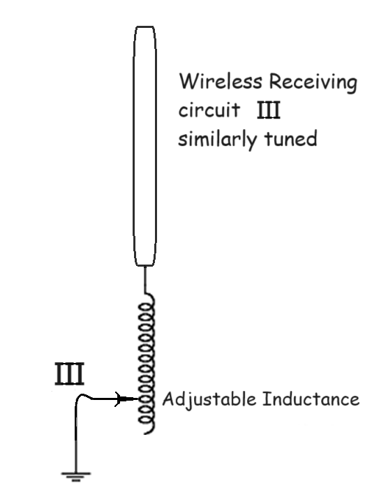
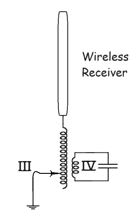
Then there is on the receiving side again the antenna circuit with an adjustable inductance, corresponding to my circuit (III) with the adjustable inductance and this capacity.
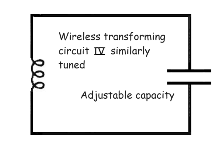
And then there is finally the fourth tuned circuit like my circuit (IV) with adjustable condenser. All is therefore a perfect, exact equivalent of the arrangements I described long ago.
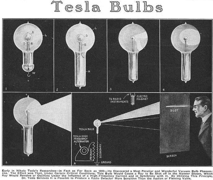
It is strongly suggested by all the available evidence that Tesla had two approaches to solve the air terminal problem. The first approach, which he tested and demonstrated at Colorado Springs: as the voltage in the transmitter develops, the air becomes conductive at lower and lower altitudes. The second approach, to be combined with the first: is to mount large, high-energy, single terminal vacuum tubes to the open air terminal of the transmitter (and perhaps the receiver) pointing upwards into the sky. These bulbs produce high-energy ultraviolet and X-rays which would ionize a column of air above the transmitter and assist in making a conductive connection to low pressure atmosphere. Tesla made sure the bulbs were covered under patent.
But remember: the ground wave transmission mode does not depend on any electrical connection to the atmosphere. The air terminal in a Tesla transmitter can be a capacitor with only one plate applied, and Tesla demonstrated this in lecture over and over again. No energy at all would be leaving the capacitor plate in this configuration.
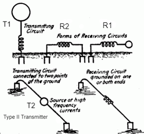
Type II Transmitter
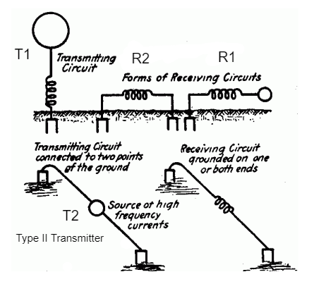
The Type II transmitter is evolved from the transmitter geometry first shown in Fig 125 in Tesla's lecture: EXPERIMENTS WITH ALTERNATE CURRENTS OF VERY HIGH FREQUENCY AND THEIR APPLICATION TO METHODS OF ARTIFICIAL ILLUMINATION, in 1891. One of the ways that the transmitter can be connected to the earth is with two metal plates separated by some fractional wavelength of the transmitter with insulated wire, and then buried in the ground.
The above sketch is a Type II configuration that was never utilized. The second passive element placed close to the active element forms a conductive connection and replaces the wires used in the Type II diagrams above. Tesla abandoned the Type II transmitter configuration when he developed more advanced, more powerful, capacitive discharge harmonic oscillators: but the Type II transmitter works fine with 447,920 for communications purposes. Both R1 and R2 receiver types will work fine with either T1 or T2 transmitter configurations. But as the transmitters get more powerful, and more expensive, it makes more sense to focus the effort into the less expensive T1 type. See Tesla Receivers -- Especially Rotational Receivers
Lines or Tubes
Instructables: How To Build a Vacuum Tube Tesla Coil (VTTC)
In his 1891 lecture, Tesla pondered on the subject of electromagnetic force and geometry. "Lines or tubes" he says... They are tubes. Larger tubes are constructed of multitudes of smaller coherent tubes. These tubes contain internal rotational geometry that prevents them from being lines, you can squeeze them down, but you cannot squeeze them into a singularity, a point, or a line. Humans have spent billions of dollars, if not a trillion, on magnetic pinches for high-energy physics applications: Everything from fusion reactors to magnetic pinch bottles, and none of this technology works very well, and it is for the most part vey big, and expensive. Much of it just does not work at all. Lab-Tesla is documenting research that points in new directions.
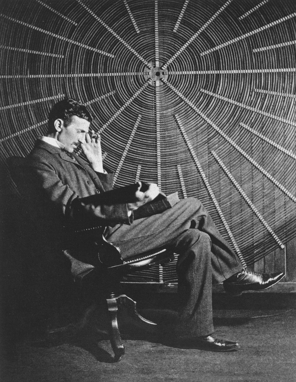
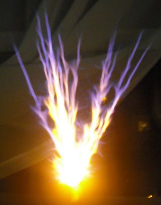
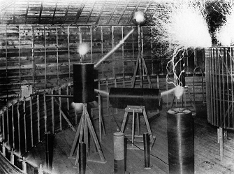
These resonant transmitter and receiver geometries documented in 645,576 and 649,621 display unusual properties. They are EMHD cymatic devices and they resonate in different modes depending on how they are applied. In stand alone mode, with the transmitter set up and operated exactly as shown in patent, but with no resonant receiver; very little energy actually leaves the conductive air-terminal. Sparking as seen in the photo above is never permitted in an operational transmitter. The purpose of a stand-alone power transmitter is to drive the conductive surface of the earth as a cymatic wave guide. A cymatic EMHD manifold forms around the insulated high-voltage air terminal, but this manifold has nothing to couple to, no where to go, and in stand-alone mode it forms a bubble or envelop (manifold) of ionized and conducting gasses around the terminal, and this bubble or manifold expands and contracts with the pulses from the generator, but the energy does not radiate; the electrons tend to cling to the conductive surface of the air terminal, and has nowhere to effectively conduct to, the impedance is very high, and the frequency is too low to radiate away. In stand alone mode, all of the energy of the transmitter is pumped into the ground terminal, the air terminal has no real output. But with a receiver located somewhere, and enough power available in the transmitter, the transmitter air terminal manifold will seek the receiver, and the receiver which is energized by the cymatically excited ground wave, produces it's own EMHD manifold around the conductive air terminal, and begins to seek out the transmitter. Eventually, a conductive channel is formed between the two air terminals of the transmitter and the receiver, and this channel acts exactly like the wire wave guide in 593,138. Once this channel is established, energy flows freely and directly from the air terminal of the transmitter, to the corresponding terminal of the receiver by conductive, capacitive, and inductive coupling.
Two linked resonators demonstrate unusual functions which are best explained by understanding that the link between them has mechanical properties, similar to a drive shaft. The best model to disclose here is of a hollow insulating tube containing a rigid center conductor, like a rod, thin metal tube or rigid wire. Once this insulating tube, with rod or wire traveling down the center, is established and connected between the transmitter and receiver, instantaneous communication and instantaneous transmission of energy are both then possible. This requires that the distance between the transmitter and the receiver has already been bridged, if this took a period of time, that time period has already elapsed. Once they are wave linked, the distance between the transmitter and the receiver in some modes, is exactly zero... They act very similar to linked quantum mechanical particles, and the reasoning for this is that the wavelink has mechanical properties; like a shaft. This shaft is very much like a rod, or rigid wire, linking the transmitter and receiver geometries together. It is important to understand these properties because they apply to astrophysics, teleportation, and advanced communications systems for deep space missions.
If you were to pump a fluid through the hose from one end to the other it would take time for the fluid to traverse the length. The same would apply if the hose was one light year long, and you sent a current pulse down the wire or rod conductor... It would take a year to arrive at the speed of light on a perfect conductor, traveling from one end of the conductor to the other. But the rigid rod or wire that travels the length of the insulating tube has no mass, and no inertia, and it is rigid. By rotating one end of the rigid wire or rod, rotating it along its axis, the rotation is seen at the receiver end instantly. The distance has already been bridged by the rod or wire, so both energy, and information, can be sent from the transmitter to the receiver instantly through rotational functions in the rigid linkage that exists between them.
Tesla specifically discussed these functions in lecture, and proceeded to follow with demonstration before the Institution of Electrical Engineers, 1892.
Tesla demonstrated rotating brush vacuum tubes in lecture. The brush rotates in synchronism with the wavelink rotation, and it can be controlled with magnets and magnetic fields, it even reacts to impulses produced by the human nervous system. The observer affects its behavior. Tesla disclosed his intention to apply this phenomena for communications in the lecture sections linked to above, and in his 1919 article in Electrical Experimenter, The True Wireless, Fig 9.
Tesla struggled to explain these concepts, but it was back in the 1890's and early 1900's and things like quantum mechanics were completely unrecognized. Tesla was sure eventually someone would come along and figure out how the system worked, with all of it's functions applied at the same time.
The quantum mechanical functions displayed by linked resonators appears to be related to the complex linkages, which are not just conductive as explained in the simple tubular waveguide model. The resonators are also linked capacitively and inductively. These complex linkages, through tubular EMHD geometries between particles, may provide a quantum mechanical force action explanation for gravity. All of the mass and energy in our Universe is effectively linked back to the Big Bang event.
723,188
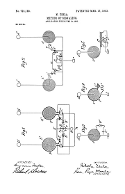
Method of Signaling - July 16, 1900
725,605
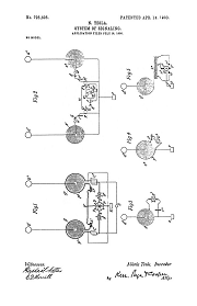
System of Signaling - July 16, 1900
These two patents above are signaling patents, intended for communications applications. They operate at a higher frequency than Tesla's power transmission patents. There is no iron in the transmitter power supply, nor is there an iron core in the resonant spiral transmitter or secondary coils. The number of turns in these spiral resonant coils are fewer than in the power transmission patents outlined previously, and they are smaller in diagram. These patents have been ruled as the source for both wireless multiplex communications and computer logic gate switching technologies. Tesla was developing a global communications system by the time these patents were filed. He was using a harmonic oscillator to produce a continuous wave output signal that was required for the transmitter carrier. But the transmitter circuit naturally produces a Fourier Transform: a broad-band of higher frequency harmonics that are coherent with the main carrier wave or "fundamental" output frequency. This fundamental frequency is set with a precision engineered rotary mercury switch or switches, and is speed controlled and powered by a precision engineered isochronous generator. The natural higher frequency harmonic functions in the transmitter that are produced by this system can be individually modulated, multiplexed, and used to send private messages, remote control equipment, etc.. There is clear documentation that Tesla was both resonating, and modulating, these higher frequency harmonics at the transmitter. The logic gate functions lead to intelligent machines. In the Tesla system it is possible to have a Tesla transmitter powering a remote device, say a robot with a wireless motor turning the hydraulic pump, and send the control information on the same manifold link that provides the power.
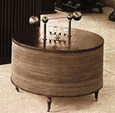
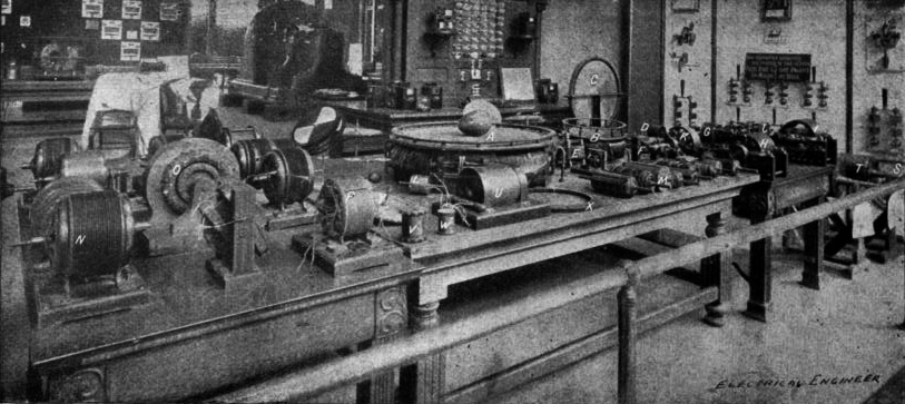
Receiving Table for Tesla Wireless
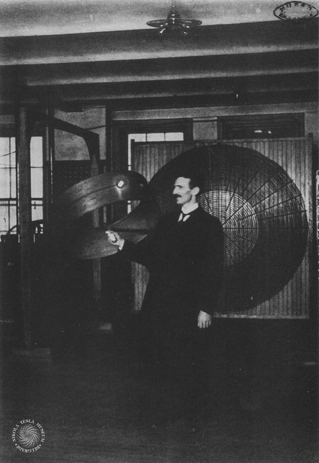
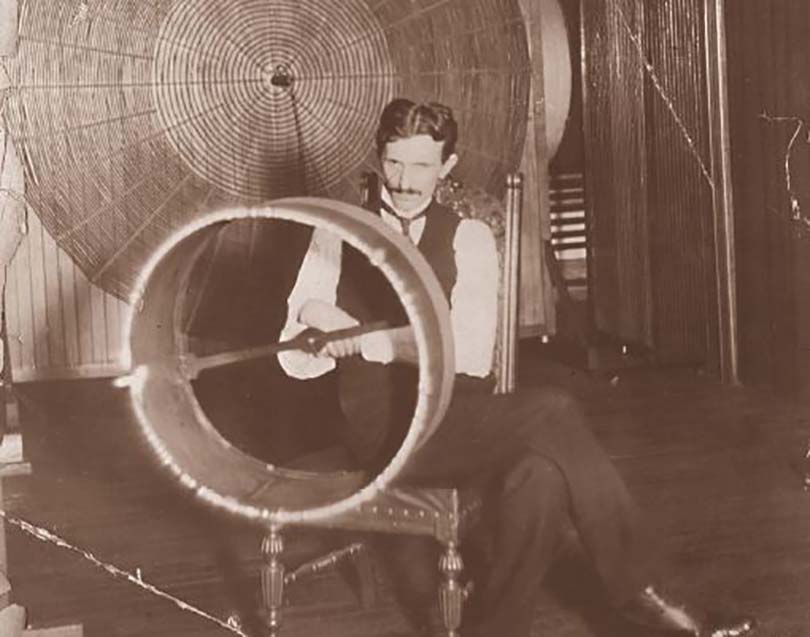
Top: Conjoint action. The cardboard drum is wound with three separate coils, all of differing length, one with a light bulb in series. Only when both coils without bulbs were energized at their specific frequencies, would the third coil containing the bulb produce enough current to light. This development led the way to modern computer technology. The image below the conjoint action demonstration shows the power that can be induced into a receiving coil held within a Tesla rotating magnetic field. There is a single winding on the coil Tesla is holding. This coil is producing spark and corona discharge from the end facing the camera. This coil is tuned to the fundamental frequency of the spiral transmitting coil in the background. The top photo shows control functions, and the photo below it shows the high-frequency power available to light bulbs and operate small motors.
In the above two patents both the transmitter side and the receiver side have two components or circuits connected together. The trick is that both circuits in the transmitter side must produce outputs of a different frequency, and both of these frequencies must be picked up in the two-part receiver before any output is produced. Tesla calls this "conjoint action" where two or more circuits must work together before a third output circuit is activated. This is the basis for modern computer AND logic gates, but Tesla demonstrated it in the lab with a simple cardboard drum tube wound with three coils, one had a light bulb. All three coils had a different length, and only when the transmitter energized two of the three coils at their specific tuned frequency, would the third coil energize and light the bulb. This was not only a laboratory demonstration in wireless energy transmission, but the conjoint action leads to secure remote control technology and the development of intelligent machines.
787,412
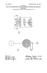
Art of Transmitting Electrical Energy Through Natural Media - May 16, 1900
The above patent shows a transmitter in stand-alone mode, most of the energy going to produce an EMHD cymatic manifold along the conductive surfaces of the earth, and a rotational receiver used for communications.
1,119,732
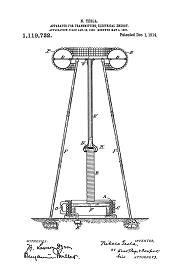
Apparatus for Transmitting Electrical Energy - Jan 18, 1902
The above patent is the Magnifying Transmitter, the final wireless transmitter patent. The electrical functions of the drive oscillator are covered in the following section:
Tesla's Electric Circuit Controllers
Precision Switching Technology
Related Patents
11,865
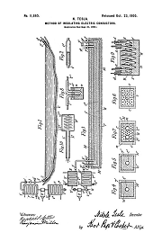
Method of Insulating Electrical Conductors - Sept 21, 1900
685,012
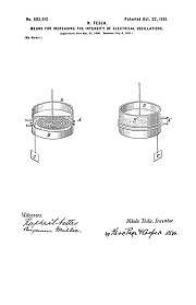
Means for Increasing the Intensity of Electrical Oscillations - Mar 21, 1900
The large transmitter that Tesla designed and began construction on at Wardenclyffe Long Island was intended to have supercooled coils in the transmitter, and ice insulated conductors in the transmission line linking the power house to the transmitter tower base. The language in 685,012 is very clear: the resonating coil must be supercooled in order to produce the intended effect. Since the coils were to be hollow copper pipes (as shown in patent 1,119,732), the simplest way to achieve this was to pump liquid air through the pipes, and it turns out that the ice that forms on the outside of the pipe is an excellent insulator. You can run the power conduits under the ground, fill the channels with water, and when the refrigerant is run through, the ice forms and insulates the conduit electrically.
The transmitter powerhouse contained refrigeration equipment, and compressors to produce liquid air, and also liquified inert gasses for Tesla's advanced mercury switches. The liquid air refrigerant would be pumped through the conductors linking the transmitter to the powerhouse. This serves a dual purpose of insulating the feed conductors to the transmitter, and supercooling the transmitter coils.
If you read 11,865 carefully you will find that the liquified air used to supercool the coils, and insulate the transmission line from the powerhouse to the transmitter, also provides pneumatic power for operating things like tuning controls. The hydraulic mains were actually pneumatic and were part of the electrical mains.
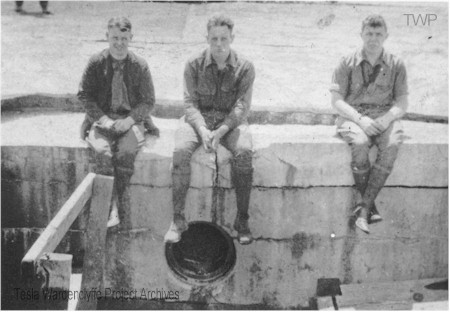
Base of tower at Tesla's Wardenclyffe plant on Long Island after removal of tower. Note the opening of the large conduit that ran from the powerhouse to the 120-foot tower shaft, one of two installed to carry electric and hydraulic mains.
Photo: Tesla Wardenclyffe Project
Quoting: 685,012: "Now I have discovered that when a circuit adapted to vibrate freely is maintained at a low temperature the oscillations excited in the same are to an extraordinary degree magnified and prolonged, and I am thus enabled to produce many valuable results which have heretofore been wholly impracticable."
So in order for the global system to be practical, supercooling the transmitter was required.
The True Wireless
Electrical Experimenter, May, 1919
Tesla's Cymatic Research
Steam Powered Isochronous Acoustic Oscillators & Generators
Tesla's Electric Circuit Controllers
Precision Switching Technology
Tesla's Electrical Isochronous Oscillators
Capacitive Discharge Power Processing
Nikola Tesla Receiver Technology
Home Appliances and Industrial Solutions
ROTATIONAL RECEPTION OF ISOCHRONOUS WAVES
Angular Displacement Receivers
Tesla's Coherer Technology
Wireless Communications Receivers
Tesla's Fluid Dynamics
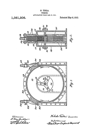
Turbine, Valvular Conduit, Pump, Fountain, Velocity Meters, Aerial Transportation
Mr. Tesla's Personal Exhibit at the World's Fair
Chapter XLII - The Martin Book
Tesla's Laboratory Power
Boiler, Steam Engine, Line-Shaft, Belts & Pulleys
The Lectures of Dr. Nikola Tesla
All lectures are formatted with legible images of the original wood cut block prints
Tesla's Complete Patents
There are 111 unique Tesla Patents
Articles by Tesla
Tesla made public disclosures of means, methods, systems, and apparatus in various articles.
Archive