Nikola Tesla's Coherer Technology
Wireless Communications Receivers
https://en.wikipedia.org/wiki/Coherer
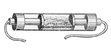
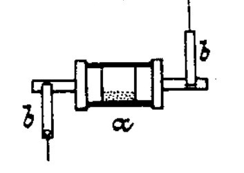
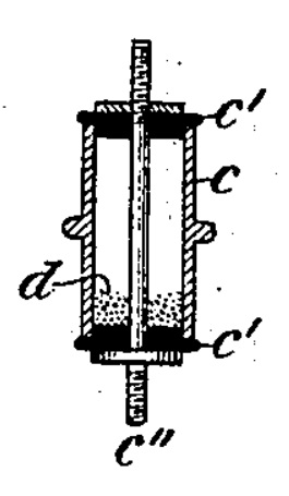
Coherence is a unique type of semi-conductor technology discovered in 1890. There are as many different types and methods of coherence as there were electrical engineers working on wireless. One popular form of coherence was to use metal particles placed in a glass tube with conductive contacts at each end. Tesla patented coherers using a "powder" consisting of fine spherical beads of nickel metal. The nickel bead powder was etched in acid solution, then carefully rinsed and dried to make the surfaces semi-conductive. Normally the particles are in a non-conductive state, but when exposed to an energy pulse, the particles shift positions into a conductive geometry, they "cohere". They remain in this conductive state until they are shaken or moved physically, and frequently these type of particle coherers were used to trigger battery powered bells: the clapper rang the bell, and at the same time, reset the coherer to receive the next impulse.
Coherers are not very effective in radiation physics applications such as in radio communications. These type of receiving switches are much more accurate, reliable, and effective in EMHD physics communications systems: properly located and connected with pickup terminals, energy from cymatically excited EMHD manifolds, that is, flowing or vibrating magnetic fields that have properties of an electrical current, or a type of electrical current where the magnetic properties dominate the electrical ones. In these applications, with this type of triggering energy: Tesla coherers are reliable, sensitive, inexpensive, and easy to operate and maintain. Serviceable units can be hand built with basic machine shop tools, and Tesla details their construction and application in the patents presented here on this page. Note: if you are interested in coherers you have to go through all of the patents using coherer technology because Tesla does not put everything in one place, ever.

Spherical nickel bead powders are commerically available from a variety of suppliers in a wide range of sizes and grades due to their unique properties, coherance being just one application for this material. Nickel alloy beads are also available.
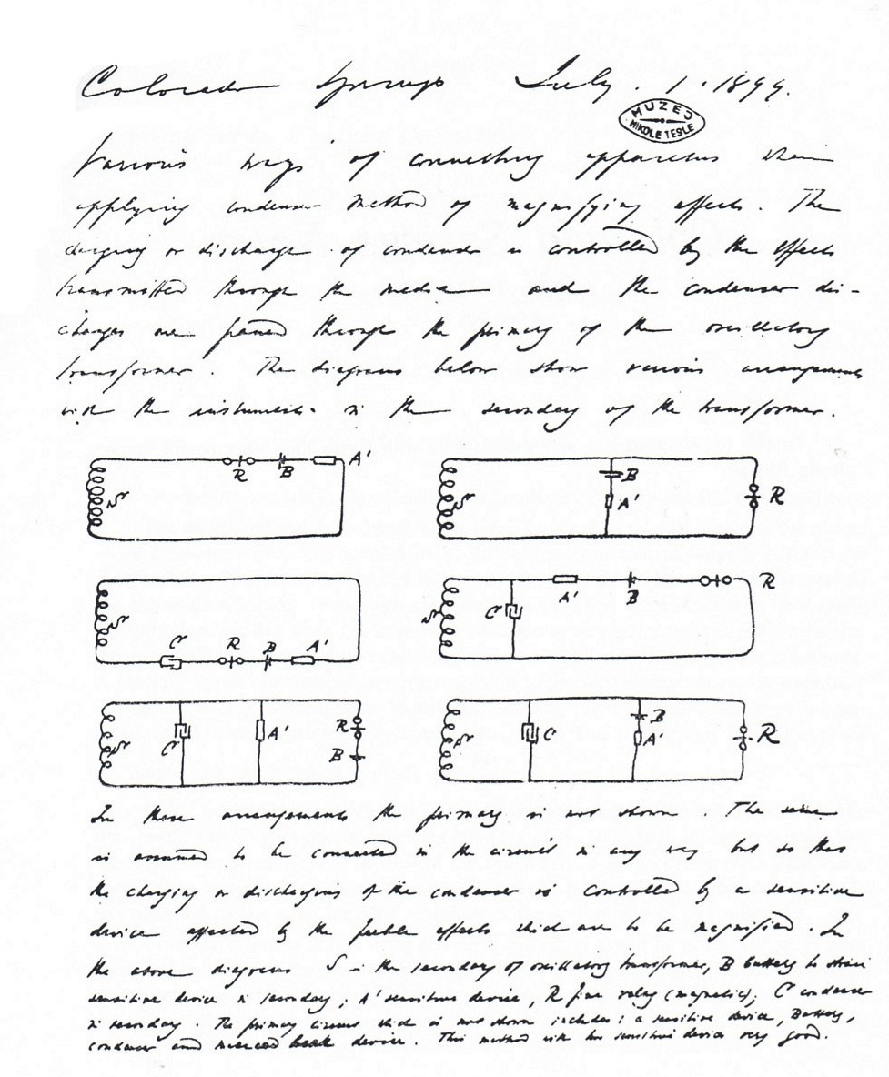
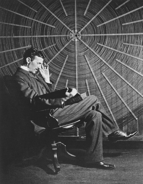
Photo Credit: https://picturesofinfinity.net/research/nikola-tesla-museum/
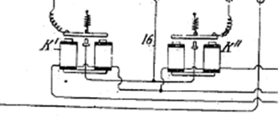
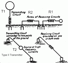
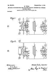
Above: Receiver circuits using coherers labeled as devices A' -- Sketched by Tesla while in Colorado Springs. In practice coherers were not placed directly in series with the grounded receiver circuit. In Colorado Springs, where the above circuits were recorded, Tesla had two ~50 foot diameter coils. The one or two turns of primary cable for the main Colorado Springs oscillator was connected to the receiver circuit components shown in diagram.

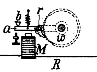
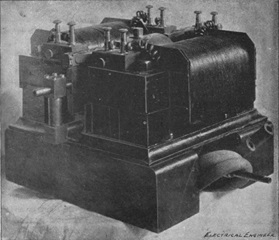
Above: Common telegraph sounder of the type Tesla used as a detector or translating device in his receiver circuits, shown as R in the handwritten diagrams documented above. In addition to sounders, small bulbs of all types were used, as were stepper motors, relays, and meters with moving needles and dials.
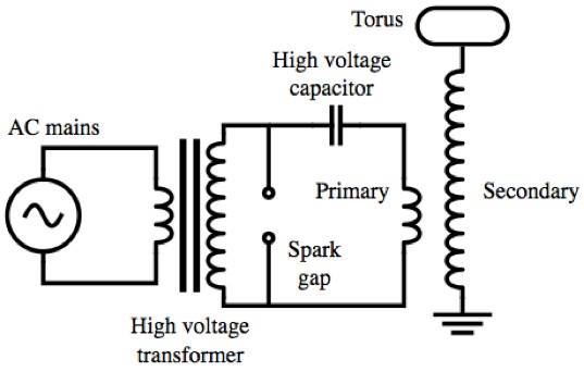
The classic Tesla Coil circuit diagram.
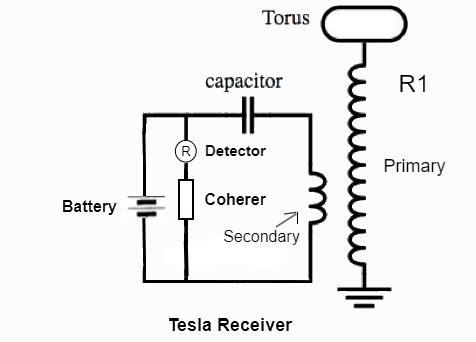
Typical Tesla communications receiver circuit.
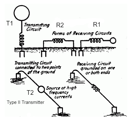
To turn a Tesla transmitter circuit into a receiver for low-power communications signals: the high-voltage power supply is switched out, usually for a battery of low voltage: and the spark gap or circuit controller switch, if used, gets replaced with a coherer or rotational receiver. The devices can be placed in various positions.
In practice the coherer is "biased" with an independant power supply: usually a dry cell battery and a variable resistor are placed in the circuit in series with the coherer and the detector. The variable resistor is adjusted until the circuit with the devices is just on the very edge of being triggered. Once the bias is properly set, it only takes a tiny component of triggering energy to cause the particles in the coherer to attract and shift into a conductive geometry. Once they are turned on, significant energy can be conducted through them from the bias power supply: and they can ring bells, flash lights, trigger relays, operate small motors etc., shown as the Detector "R" in the receiver diagram above.
One problem with coherers is bias leakage. When the coherer is properly biased and under electrical tension, electrons bounce from particle to particle between the contacts, producing a leakage current. This current increases the closer to triggering the coherer is biased, and in practice they slowly drain the battery down, losing their sensitivity at the same time. For a receiving station a stable voltage DC power supply is mandated in order to effectively bias the coherers and account for leakage current.
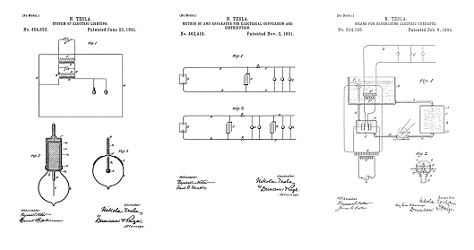
Small stepper motor used in a receiver circuit. US Patent 685,957. Tesla was a clock-maker and he employed nearly identical stepper movements in 514,169.
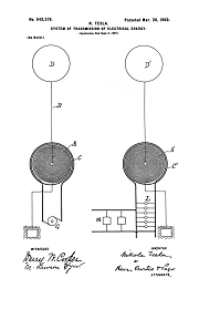
The energy to trigger the coherer is picked up by the large grounded coil, R1, and induced electromagnetically into the receiver circuit shown in diagram (and in photo). See US Patents 645,576 and 649,621, the "working devices" shown on the receiver side (right) in the patents are lamps and motors being powered wirelessly by the transmitter: but Tesla stated that before lamps and motors can be applied you have to be able to use sensitive devices: coherers and rotational receivers. As the power levels in the transmitter were developed, or if the receiver was located close to the transmitter: first the battery can be dispensed with, then the coherer can be removed.
Tesla's global system employed a broad-band harmonic oscillator as the main transmitter. Tesla photographed at least 9 harmonics in the Colorado Springs Master Oscillator. These harmonics were so powerful that even the highest harmonics, using very small high frequency coils, were resonated to spark. These are the frequencies where Tesla intended to employ coherers in tuned receiving circuits to switch on things like motors and lights which would be powered by the fundamental frequency produced by the transmitter. This leaves the 3rd through at least the 9th harmonics available with enough amplitude to provide communications signals to both rotational receivers and coherers. The spark photo of the harmonic functions taken at Colorado Springs indicates that Tesla considered the 8th and 9th harmonics to be usuable, probably just for coherers.
Tesla designed his own coherer elements, and applied them in rotational systems which turned the coherer and reset the particles after they were triggered. Coherers could be rotated continuously in these systems, the speed of rotation is variable. Or they can be applied in a fixed position to receive an impulse, and then when they are triggered a mechanism rotates them into a new fixed position ready to trigger again on the next received impulse: this technology was used to process the control signal to the wirelessly controlled torpedo boat.
Note: The relays shown in 613,809, below, are basic modifications of the telegraph sounder pictured above.
613,809
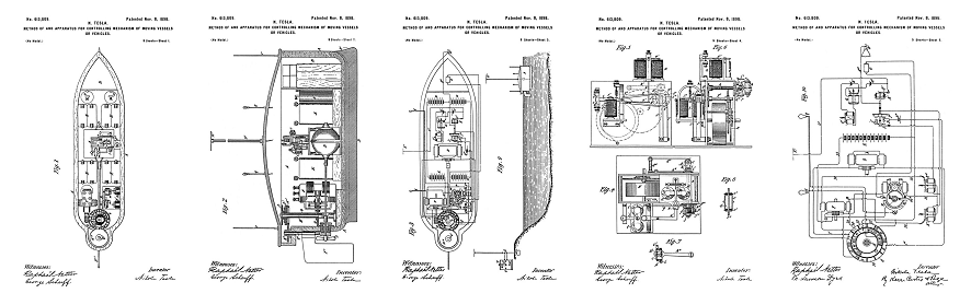
Method of and Apparatus for Controlling Mechanism of Moving Vessels or Vehicles - July 1, 1898
685,954
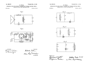
Method of Utilizing Effects Transmitted Through Natural Media - Aug 1, 1899
685,956
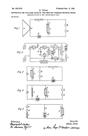
Apparatus for Utilizing Effects Transmitted Through Natural Media - Aug 1, 1899
Related Patents
723,188
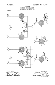
Method of Signaling - July 16, 1900
725,605
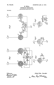
System of Signaling - July 16, 1900
Nikola Tesla Receiver Technology
Home Appliances and Industrial Solutions
ROTATIONAL RECEPTION OF ISOCHRONOUS WAVES
Angular Displacement Receivers
Nikola Tesla on Mechanical and Electrical Oscillators
Chapter XLIII - The Martin Book
Tesla's Electrical Isochronous Oscillators
Capacitive Discharge Power Processing
Tesla's Cymatic Research
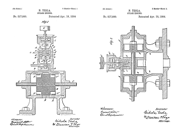
Steam Powered Isochronous Acoustic Oscillators & Generators
Tesla Transmitters
Wireless Transmission of Electrical Energy
Archive