Rotational Reception of Isochronous Waves

Angular Displacement Receivers
The operational principal here is that an inducing cymatic manifold produces voltage differences between two displaced metal plates. By connecting the plates with wires to a commutator drum, and then spinning the drum in perfect synchronism with the generator, you can charge a capacitor with the rectified energy.
A second commutator drum is used to periodically discharge the capacitor into a receiver of some type: flashing bulb, relay tick, whatever...

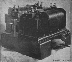
Above: Common telegraph sounder of the type Tesla used as a detector or translating device in his receiver circuits, shown as R in his handwritten circuit diagrams and in patents listed on this page. In addition to sounders, small bulbs of all types were used, as were stepper motors, relays, and meters with moving needles and dials.
In order for the receiver to work, the commutator used to rectify the vibrational energy must be rotated at precisely the same speed, or fractional speed, of the generator. This rotation can be supplied by wind-up clockwork, steam powered clockwork, or a synchronous motor in a frequency locked rotational alternating current network.
The pickup brushes on these commutator drums must be capable of angular displacement in order to properly align the wave form of the transmitter to the capacitor. These commutator drums are equipped with both slip-rings for continous connection while they are spinning, and segmented insulated sections for rectification, and the timing of the output device triggering.
As one commutator drum is rotated in synchronism with the generator/transmitter, it typically takes a few switch cycles, or commutations, to store enough energy in the capacitor to trigger the output device. The second commutator drum is either rotated at a slower rate to allow time for the capacitor to charge, or the commutator brushes are set to allow a longer interval of time to elapse, allowing the capacitor to charge, before switching in the output device.
In some cases, electric circuit controllers can be used to rectify the energy to charge a capacitor in the receiver.
Tesla notes in patent that if you are close enough to the transmitter, or if the transmitter is powerful enough, and the frequency is low enough, you don't need the commutator to charge a capacitor.
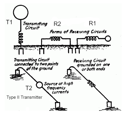
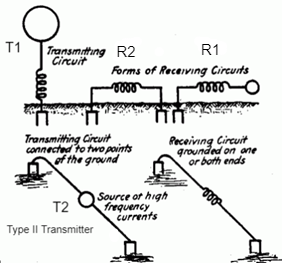
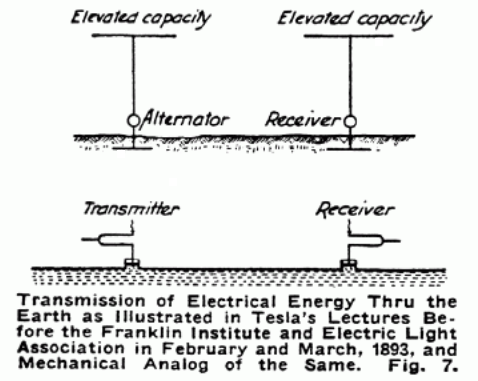
The transmitter geometry used in conjuction with these patented rotational receivers are described in US Patent 787,412, below, but it was first introduced in the following lecture in Fig 125:
685,953
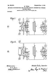
Method of Intensifying and Utilizing Effects Transmitted Through Natural Media - June 24, 1899
685,954
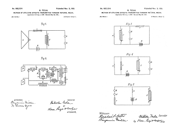
Method of Utilizing Effects Transmitted Through Natural Media - Aug 1, 1899
685,955
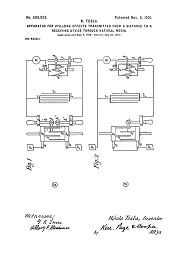
685,956
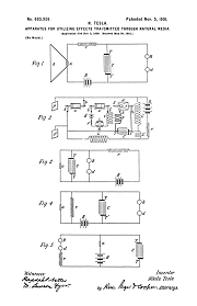
Apparatus for Utilizing Effects Transmitted Through Natural Media - Aug 1, 1899
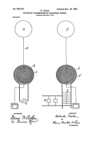
787,412
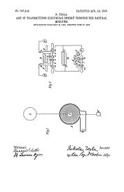
Art of Transmitting Electrical Energy Through Natural Media - May 16, 1900
Related Patent
447,920
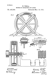
Method of Operating Arc Lamps - Oct 1, 1890
Nikola Tesla's Receiver Technology
Home Appliances and Industrial Solutions
Tesla's Coherer Technology
Wireless Communications Receivers
Tesla's Cymatic Research
Steam Powered Isochronous Acoustic Oscillators & Generators
Nikola Tesla on Mechanical and Electrical Oscillators
Chapter XLIII - The Martin Book
Tesla Transmitters
Wireless Transmission of Electrical Energy
The True Wireless
Electrical Experimenter, May, 1919
To the Archive Page Discussion on Tesla's Technology