Nikola Tesla's Electric Circuit Controllers
Precision Switching Technology
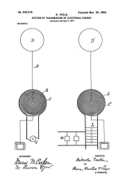
Tesla's electrical oscillators were switching fully charged capacitors into short heavy coils. As the voltage developed in these capacitors, the ability to switch them cleanly from charging mode into discharge mode, and then back to the charging circuit again, proved to be a true engineering challenge.
Tesla introduced rotary switching technology in lecture in 1893.
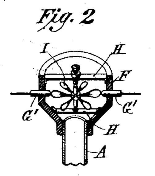
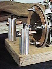
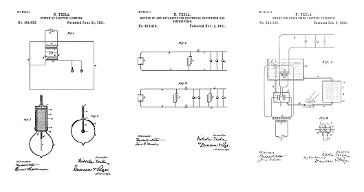
Also in 1893, Tesla patented a unique rotary switch as part of an electrical oscillator system in 514168, Fig 2, above. The oscillator coils, capacitor, and the switch were insulated in an oil bath with a cooling loop. A small two-phase Tesla induction motor turns a pump. This is one of the first occurrences anywhere in the historical record of a small electric motor being used to power individual equipment, rather than have a power take-off belt from a line shaft. The motor powers the cooling loop pump, and the oil stream is placed in front of a Pelton wheel, which spins, and makes, and breaks, the switch contacts. The oil also quenches the arc that forms on the switch contacts, and the cooling loop removes the heat. This oscillator and rotary switch were designed for continuous duty and the output current was used for shop and laboratory lighting, as well as for research, development, and demonstration applications.
By 1898 Tesla was patenting rotary switching technology using jets of mercury making and breaking circuit contacts in a pressurized environment of inert gas, US Patent: 611,719.
A modern Tesla Coil synchronous rotary gap switch
Tesla experimented with air blasts and magnets across the spark gaps to quench the arc in his first oscillators, but the advantages of positively switching circuits, some type of controller, are so great that Tesla began a serious research and development path. There are two rotary techniques that emerged. The first is a simple rotary spark gap pictured above: in these rotary switches the contacts pass close to each other and a spark jumps the gap briefly before the contacts move away from each other. In the second, a true circuit controller, liquid mercury makes a positive electrical contact between two terminals and there is little or no arcing. The rotary spark gap requires a high voltage power supply and a high voltage capacitor to function, they don't work so well below 5000 volts because the spark does not reliably jump the gap. A circuit controller on the other hand makes a positive contact regardless of voltage, they can be used to switch receiver circuits of very low voltage for instance, and you get much more control over things like dwell time, but... The power handling requirements for a large transmitter...
When a fully charged high-voltage capacitor is switched into the tank circuit coil in the Tesla oscillator; to be applied say for a global ground-wave transmitter: the peak power delivered to the coil can easily reach the megawatt range, and Tesla stated that the designed peak power for the Wardenclyffe transmitter was one gigawatt: this estimate is completely supported by the photographic evidence. Hundreds of amps at tens of thousands of volts must be handled by the switch. Once the energy pulse is delivered, the capacitor has to be switched back to the charging transformer for the next cycle... And they can be cycled at rates of hundreds or even thousands of times per second. If the contact points of such a switch are exposed to oxygen, each cycle vaporizes and burns away metal from the surface of the switch. The vaporized and burning metal atoms become part of the plasma channel, the electrical fire, that must be quenched in order to make the switch function.
The problems encountered in trying to switch fully charged capacitors into the output coil, and then back into a high-voltage charging circuit, are much, much greater than the problems involved in switching a low-voltage DC generator into an arc-light circuit with a commutator... And that is an engineering challenge in itself that Tesla patented on.
When you are cycling high-voltage capacitors you literally have to extinguish an electrical fire, an arc, that forms on the switch contacts at a moment in time just before the switch is closed, and whenever the switch is opened again. Putting out this electrical fire is called "quenching", and in high-voltage applications using big capacitors, extreme engineering is required to make, and break, these switch contacts effectively.
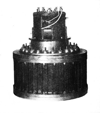
In order to solve these problems Tesla developed specialized synchronous motors, designed to be powered by isochronous generators. The motors were constructed around a hollow armature containing a compartment and mechanisms to spin a quantity of liquid mercury. In some circuit controllers a metal vane was spun, plunging the edges into the liquid mercury to make and break the contact. In other controllers the mercury was scooped up and flung out in jets, the impact of the jets against vanes or other jets, made and broke the electrical contact. After running for awhile all the oxygen in the sealed compartment gets consumed, and the contact erosion is reduced. In later patents, the rotary mercury switches were run with the sealed internal compartments pressurized with inert gas, the contacts were made between two jets of mercury, and many of these problems were resolved. A switch designed for a large transmitter could be several feet in diameter.
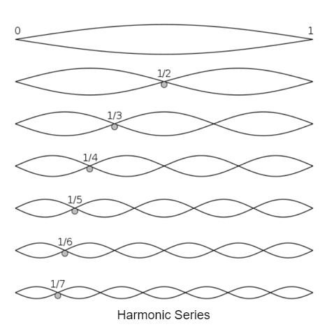
The end goal of this switching technology is to deliver a string of perfectly timed pulses of electrical energy from the discharge of a high-voltage capacitor into a circuit that transforms the energy into a periodical pulsitory wave of the same frequency as the switch rate, called "The Fundamental", which is linked together continuously, with a broad band of harmonic frequencies all shared on the same conductor. This is technically feasible using this technology, essentially converting a train of capacitor discharge spikes into a complex pulsitory wave output to the transmitter terminals. Using a DC power supply to charge high-voltage capacitors to the same energy level for each cycle, and then with precise switching technology to discharge the capacitor in a single pulse into a tightly coupled primary/secondary coil: the secondary coil produces a broad-band harmonic response. - The third harmonic in this excited secondary coil is the first pure sine wave. The "fundamental" frequency is where most of the transmitter output occurs: but Tesla identifies at least 9 higher frequency harmonics produced by this type of broad-band harmonic oscillator. Tesla demonstrated his ability to process power using this technology in large scale experiments performed in Colorado Springs, below.
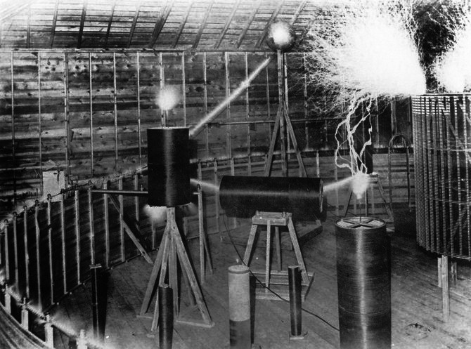
This photo documents that Tesla is deliberately exploiting a natural harmonic transform, or "Fourier Transform" in the Master Oscillator.
See Tesla's article: The Problem of Increasing Human Energy, Figure 5.
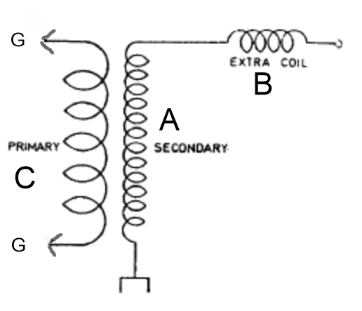
The Master Oscillator surrounds the spark demonstration experiment photographed above. On the right side of the spark photo is a coil standing on wooden legs, highly energized, and this is called "the Extra Coil" and is labeled "B" in the advanced transmiter patent 1,119,732 that Tesla is developing here. The diameter of the Master Oscillator is about 50 feet, just over 15 meters. -- The top turn of the secondary coil of the Master Oscillator A is highly excited, you can see corona spraying off the top turn in the lower left, it is mounted on insulators as it goes around the experiment. There is a direct conductive coupling, a cable connection, that is not in view in the above photo [but can be seen in the lower left here], between the top turn of the Master Oscillator and the bottom turn on the Extra Coil: this connection is clearly shown in the diagrams. This "Extra Coil" - B - in the diagrams, is tuned to the fundamental frequency produced by the spark gap or circuit controller switch rate. This extra coil it is emitting an intense EMHD manifold of spark and corona. The top turn of the Master Oscillator, labled A, contains a broad-band of frequencies all vibrating together in harmony on the same conductor. Another name for this is a harmonic oscillator. Energy is input at one specific frequency, in this case a string of perfectly timed capacitor discharges using one, or more patented rotary switches. The secondary coil response includes the "fundamental" frequency and a broad-band of higher frequencies. Through a naturally produced Fourier Transform, the output of the Extra Coil is a power signal, as demonstrated in experiment, and this output was to be used to drive the transmitter: the carrier wave. This pulse carrier was intended to power small receiving devices like synchronous motors and reading lamps. The smaller coils are individually tuned to the higher frequency harmonics produced by the Master Oscillator, these smaller coils also fairly clean sine waves, and these higher frequency sine waves all travel together in harmony on the carrier pulse wave produced by the Extra Coil.
Photos taken inside the Colorado Springs laboratory show that the "Extra Coil" was tuned to the "fundamental frequency", set by the spark gap or circuit controller switch rate. Starting with the third harmonic frequency of the oscillator/transformer/transmitter, and moving into higher frequency harmonics with a "harmonic series", are pretty clean sine wave frequencies or "channels". The smaller coils were tuned from the 2nd through at least the 9th harmonic. The prototyping circuit at Colorado Springs was so powerful that even the 9th harmonic was tuned to spark in the photo.
The above figure shows the mathematical solution of a Fourier Transform of a square wave or spike signal of constant frequency. The black trace represents a string of precisely controlled discharges of a capacitor (labeled G in the referenced patent) that is being switched back and forth between the charging circuit, and the primary coil labeled C in patent 1,119,732. - Tesla calls the circuit switch rate 'the fundamental" frequency. - The red trace is the harmonic response in the secondary coil labeled A in the patent. The first harmonic follows right with the energy spike, it too is "the fundamental", and the freqency is set by the circuit controller or controllers switch rate. The second harmonic dips negative, just before, and after, the first. The third harmonic is the highest frequency wave form shown in the figure above, it is the first pure sine wave produced by this geometry, and the amplitude of all of these third harmonic waves are equi-distant, both above and below, the base line. There are higher frequency harmonics that are not shown on the above chart, but are seen in practice in the experiment photos above and below.
As a general rule in practice: the shorter the pulse duration of the capacitor discharge, and the greater the accuracy of the pulse timing and amplitude, the higher resolution the third harmonic output will be = closer to a pure sine wave from the Extra Coil, shown partly on the right side of the spark photo previous.
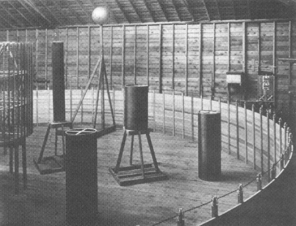
In the above image the "Extra Coil" is on the left. The smaller coils are all individually tuned to the higher frequency harmonics produced by the Master Oscillator. Most of the power of the transmitter would be output at the fundamental frequency, and the higher frequencies were to be used for communications and control applications. The photos here indicate Tesla was resonating or processing these higher frequency harmonics produced by the Master Oscillator. In communication applications each harmonic represents a separate channel, and each one can be processed separately and individually. Tesla's receivers were based on two or more separate channels cooperating together.
It is important to understand that US Patents 723,188, and 725,605 cover the modulation of the higher frequency harmonics for communication purposes. Tesla discovered that the third harmonic carrier wave can power lights, and small wireless motors, and that the naturally produced higher frequency harmonics in the transmitter can be individually modulated for communication and control purposes. Wireless remote control robots is just one technology that will result from this research. But in order to execute a clean Fourier Transform and harmonic series, the circuit controller functions need to be incredibly precise. Tesla spoke of this over and over again, saying that the discharge of the capacitor must be like a hammer blow, and then once the blow is delivered, the capacitor must be instantly isolated from the discharge circuit, so that there is no time for the hammer blow to bounce back to the capacitor. Each blow must follow in perfectly timed sucession, and each one must deliver exactly same energy in Joules: which means the capacitor(s) need a DC power supply so that they are charged to exactly the same voltage each time they are cycled.
It is also important to understand that dorking around in the laboratory and gathering spark photos does not at all require a pure sine wave output from the circuit. If you are taking photos to demonstrate a harmonic oscillator, and you are doing it by making the oscillator spark, you are not set up to operate as a transmitter. In this circumstance you can still gather enormous amounts of data to be applied when the same circuit is configured to produce sine waves and operate as a transmitter. All of the spark photos that Tesla took were just him dorking around with the circuits. The photos were taken to demonstrate peak power and efficiency. In these circumstances you don't need things like the most precise switching, pretty good switching will get a decent photo, same goes for the power supply... You can drive a Tesla harmonic oscillator with alternating current: Tesla did and took photos of it. But when you set the circuit up to actually produce sine waves and transmit a signal, you use a high voltage DC power supply. It is the same difference as taking the alternator 447,920 and demonstrating it in lecture with a steam driven line-shaft. You can get excellent demonstrations using line-shaft power to drive the alternator, but it is completely useless for any type of communications applications because all of the flexing, twisting, vibration, overspeeds and underspeeds that are inherent to line-shaft technology prevents the output signal from being clean and stable enough to use to transmit messages. If you are using a Tesla alternator to drive a transmitter, it has to be shaft driven from a frequency stable motor.
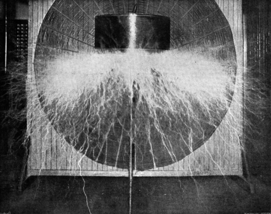
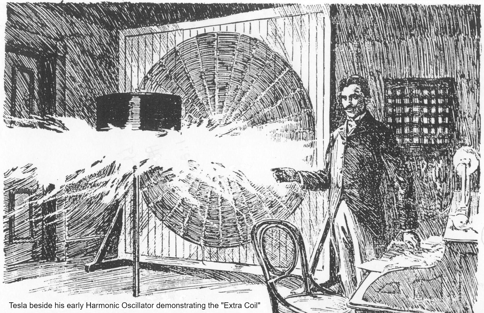
This is the actual photograph that the above artist illustration is based on. This is an important image taken in the NY laboratory before Tesla went to Colorado Springs. This is the Extra Coil resonating to spark in a Harmonic Oscillator. The position of the coil, 90 degrees off-axis from the orientation of the primary/secondary coils in the rear of the photo, tells us this coil is not inductively coupled. The energy it is resonating is supplied by a cable connection leading back to the center of the spiral secondary winding. The secondary is 8 feet in diameter and is mounted vertically to save floor space, but the circuit being used here is identical in every respect to the circuit used in Colorado Springs, shown higher up the page. Tesla designed and built small desktop oscillators that operated harmonically, he then developed a large oscillator in the New York laboratory, as large as the space would permit. Then he went to Colorado Springs to be absolutely sure that the technology could be scaled up to power a global transmitter using a large, low frequency, harmonic oscillator. In this application your working model can operate with 100 watts input power, but to get to really low frequencies, below 30,000 cycles per second, you need really big capacitors, and really big coils... Which was fine with Tesla because that also means a lot of power. So much power that the broad-band of output frequencies could be assigned different tasks.
609,245
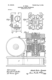
Electric Circuit Controller - Dec 10, 1897
609,246
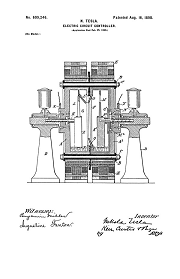
Electric Circuit Controller - Mar 12, 1898
609,247
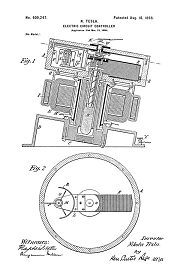
Electric Circuit Controller - Mar 12, 1898
609,248
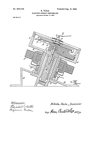
Electric Circuit Controller - Mar 12, 1898
609,249
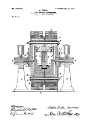
Electric Circuit Controller - Mar 12, 1898
609,250
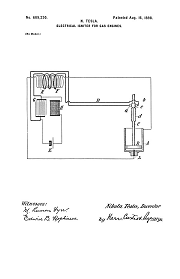
Electrical Ignitor for Gas Engines - Feb 17, 1897
609,251
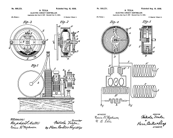
Electric Circuit Controller - Dec 2, 1897
611,719
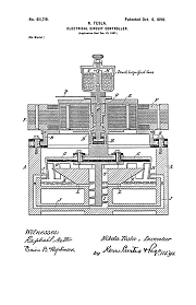
Electric Circuit Controller - Feb 28, 1898
613,735
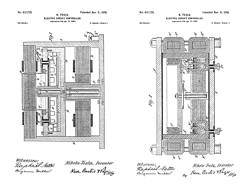
Electric Circuit Controller - Apr 19, 1898
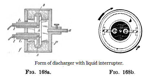
Mechanical break with two oppositely rotating discs used for the purpose of increasing the number of breaks and alternating oscillations practically undamped. (Subsequently patented by others.) - [This was line-shaft driven at first, then directly shaft driven, using two identical synchronous motors, one turning the opposite direction on each side. These motors were driven with a 2-phase isochronous generator.
"By the way, now, for a first time you see my apparatus on Houston street, which I used for obtaining oscillations, damped and undamped as well. But it was necessary to state that while others, who had been using my apparatus, but without my experience, have produced with it damped oscillations, my oscillations were almost invariably continuous, or undamped, because my circuits were so designed that they have a very small damping factor. Even if I operated with very low frequencies, I allways obtained continuous, or undamped, waves for the reason that I designed my circuits as nonradiative circuits." - N. Tesla
This was one of the oscillator circuits Tesla used in the New York lab. The square conductor at the top of the image was a loop of cable run around the ceiling molding. The diagram inside the circuit is the rotary switch design Tesla used to switch the capacitors from charging to discharge mode. Typically in this arrangement the rotary switch was directly driven from the generator shaft. Transmitter circuits like this were first disclosed in Tesla's lecture before the American Institute of Electrical Engineers in Fig 127. The receivers Tesla developed were photographed in both the NY and Wardenclyffe laboratories.
Use of multi-phase generator with mechanical break. Experiments in the laboratory at 35 South Fifth Avenue and subsequently.
Image Credits: Gary Peterson, http://www.tfcbooks.com/
Related Patent
1,119,732
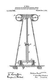
Apparatus for Transmitting Electrical Energy - Jan 18, 1902
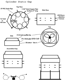
RQ/TCBOR Cylinder Static Gap
Tesla introduced his resonating coil technology in lecture in 1891
Electrical Oscillators
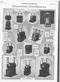
Electrical Experimenter, July, 1919
Tesla Transmitters
Wireless Transmission of Electrical Energy
Tesla's Electrical Isochronous Oscillators
Capacitive Discharge Power Processing
Tesla's Cymatic Research
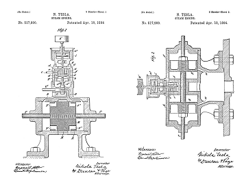
Steam Powered Isochronous Acoustic Oscillators & Generators
THE TESLA EFFECTS WITH HIGH FREQUENCY AND HIGH POTENTIAL CURRENTS

Chapter XXV - The Martin Book
Tesla Fluid Model
Unified Field Mathematics
To the Archive Page Discussion on Tesla's Technology