Nikola Tesla on Alternating Currents
Legal Deposition, New York, New York, 1916
Edited by Leland I. Anderson
Counsel
Please recount the history of your work with alternating currents and their application to wireless telegraphy, telephony, and wireless transmission of power.
I. High Frequency Alternators
Nikola Tesla
Work on high frequency alternators was begun by me in 1888, in my laboratory at 89 Liberty Street. I had just completed my system of power transmission, which is now universally adopted, but several problems yet remained to be solved. One was to run my induction motors at very high speeds; another one was to adapt them to the then existing alternating circuits of supply of 133 cycles. These two problems, although they were diametrically opposite, both required the use of laminated structures with a great many poles or polar projections, and I constructed quite a number of these with the object of improving along the lines indicated.
Among these was an alternator with 24 poles, which gave me 12 cycles per revolution. This I used originally in running some small induction motors at speeds up to 200 [revolutions] per second. Occasionally, however, I would use this alternator in other experiments, with transformers, etc., and condensers, and then by running it at high speed (10,000 RPM) developing something like 2,000 cycles [per second], which phenomena were entirely new. This, of course, interested me very much, but the work was interrupted in 1888 when I had to go to Pittsburgh to attend to the manufacture of the motors.
On my return to New York the next year, that was early in 1889, I engaged a laboratory at 175 Grand Street, close to Center Street, and there is where I undertook to design and construct the first high frequency machines.
I had at that time already perceived enough to get the idea that energy could be transmitted without wires. It was of no consequence to me at that time whether it was to be used for telegraphy, or telephony, or power transmission. I was on the problem of transmitting energy without wires; and as it is my custom always to analyze scientifically every problem that I undertake to solve, I devoted a great deal of thought to how to attack that problem, and the following crystallized out.
It was evident to me that wireless transmission of energy, if it could ever be accomplished, is not an invention; it is an art. Bell's telephone, Edison's phonograph, or my induction motor were inventions, but the wireless transmission of energy is an art that requires a great many inventions in combination.
We are living on a planet that is rushing through space; this planet is partly conducting and partly insulating. If it were all conducting, or if it were all insulating, we could not transmit energy without wire. It is only because it is partly conducting and partly insulating that a glorious future for man is reserved through the application of this art.
The steps to be taken which I recognized then as absolutely necessary were, first, that I had to produce electric oscillations of the required character. Now, granted that I had them, it still remained to be shown how these oscillations could be transformed into some sort of vibratory energy capable of penetrating into the distance. Therefore, the second step was the transformation of these oscillations into such form of energy as would go to a distance. To develop methods of and apparatus for reception, to collect the energy at any point, was the third step. The fourth step was to isolate the energy. If I simply transmitted energy in all directions without regard to its use, then that energy would be simply lost in space, and it would be no economical system. Consequently, I had to devise means to isolate that energy, and this problem again presented itself in two aspects, active and passive; that is, I had to make the transmitter noninterfering, and I had to make it noninterferable. Those are not two identical problems, but both had to be solved. Finally, as to the fifth step, I found that we could never transmit energy, or construct our machines and apply them with understanding, unless we discovered the laws according to which this energy flows through the planet, laws which would enable us to calculate accurately the energy we are to receive at any point, and to design our machines to suit the work.
In reviewing these objectives, what I am going to show you, step by step, is how I proceeded until I finally realized my dream, and, in 1899, produced a transmitter of greater power than probably all the combined transmitters put up today, and, furthermore, perfected an apparatus by which unlimited energy can be transmitted very economically, thousands of horsepower if necessary, from one small, compact plant, much smaller than that at Sayville or Tuckerton. [*1]
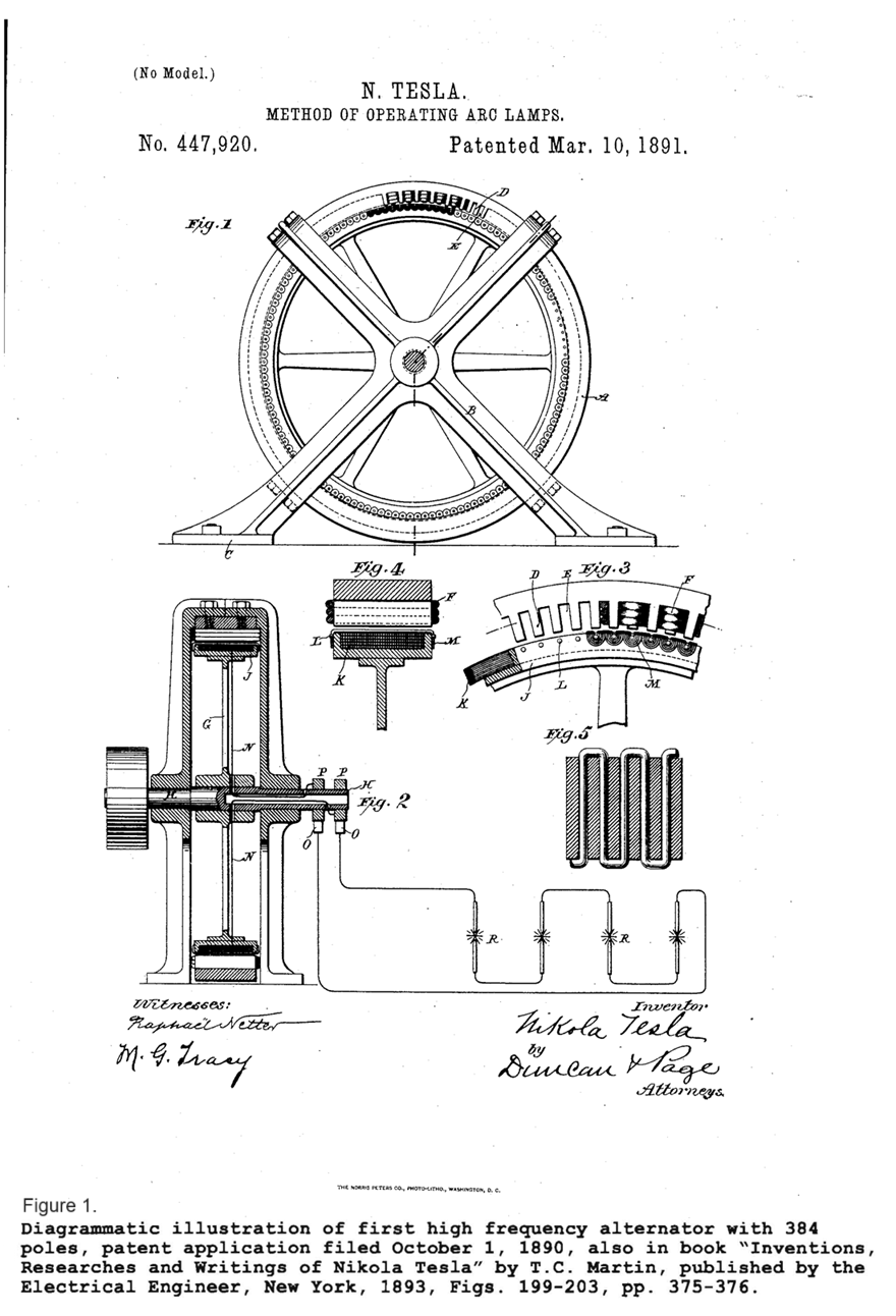
The drawing [Fig. 1] shows the first step toward the evolution of a generator, or transmitter, which may be used to flash energy to distances, under practical and economical conditions. This machine was described by me in U.S. Patent 447,920, of March 10, 1891.
It was the first high frequency alternator that was exhibited, and with which tests were made in public, although I had made alternators of high frequency, as I said before, as far back as 1888. This was a machine from which I could get from 10,000 to 20,000 cycles. We used to say, in old times, "alternations"; this term has been loosely employed.
There has been an impression produced that my early machines were rather experimental; but as a matter of fact, the design and construction of machines was my specialty and prior to undertaking this, I had spent eight years in doing nothing but designing machines. Therefore, the results which I showed with this machine, and which I put before the world in 1891, are results with a machine that I could not, with all my present knowledge and experience, and all the devices of the art, improve one-half of one percent. And any other engineer, no matter who he be, would have that same hard time as myself because in this I embodied every little device that was available. I utilized to the full and got the maximum out of the materials. I had the lowest armature resistance which could be obtained, I had the lowest self-induction, I had the highest periphery speed, I had the greatest output, far greater than any alternator that has ever been built since that time. In fact, I united in this machine features which no other that has been designed since has ever combined.
Furthermore, the currents I developed were perfectly sinusoidal. That may have been known to other experts, that the currents should be sinusoidal, because that follows from certain theoretical researches; but remember that I had invented the "rotating magnetic field," that the very production of that field was based on the use of quantities which wax and wane alternately in accordance with the law of the sine as, I have pointed out in a paper read before the American Institute of Electrical Engineers in 1888, when I presented my induction motor before that body. Therefore, everything was done in this machine that could be done to secure advantage by every possible device known to engineering.
Referring to the drawing [Fig. 1], I employed a ring of the finest iron, and a steel disc with a peculiarly arranged ring, capable of rotating at 1,400 feet per second, safely. No such velocity has ever been approximated in any alternator. I had, furthermore, an armature resistance in this machine of only 0.5 ohm. If I would have had, say, 6 ohms, which is typical of such an alternator, the machine would have been burned out. Even at 0.5 ohm, I had a hard time to operate it when I really had the greatest resonant rise.
I used a trick [in this machine] which enabled me to get a big output, and you will see how I accomplished it. I constructed my rotor with just one layer of thin wire, and by a special process I baked this wire so that it formed a solid mass with the rotor, and the centrifugal force, no matter how how high the speed, could not tear it off. Then I made my field very small. The result of this was that I had a tremendous ventilation which enabled me to put through the field a current of 25 or 30 amperes per square millimeter, and out of the armature I could easily take 30 amperes per square millimeter. You know, in machine design, if you take out four to four-and-one-half amperes per square millimeter, that is a great performance. I defy anyone to take out of the conductor [of these conventional machines] more than five or six amperes per square millimeter. But, I designed this machine so that I could have 30 amperes per millimeter in the armature and nearly 30 amperes per millimeter in the field on account of the great ventilation.
So, therefore, when I show this machine, I have shown the most advanced machine in wireless that has ever been produced up to this date. People, of course, have managed to use a turbine, but that is a subsequent development. If I had had a turbine to drive this machine, I would have done much better. Later on, however, I will show you a machine which I designed specifically for the turbine. I have recently heard that, as a result of years of work Hogan [*2] reported that they came to just exactly the same machine which I exhibited in 1892 and 1893, with which I showed experiments to Helmholtz, and which was a piece of apparatus known all the world over from pictures; yet they have been doing nothing for years and years but experimenting in this particular field.
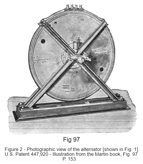
This machine [Fig 2] was exhibited before before the American Institute of Electrical Engineers [1891], where I showed my first experiments, and in these experiments, as I shall state in a few words, I obtained some striking results, which were the starting point of this whole development.
Unfortunately, that [Fig. 2] is a reproduction from the only picture I have. This machine was destroyed in the fire that annihilated my laboratory in the Spring of 1895, and I had nothing left of it but a little piece. That photograph [was] taken from an old, very poor print; but it shows the general arrangement of the machine.
This machine I operated at Columbia College with about 5,000 cycles; later on I attained 23,000 cycles running it at a higher speed, and it was in every way a most satisfactory piece of apparatus. It was used by me in experiments with wireless telephony, telegraphy, and all sorts of experiments until it was destroyed. When I published the results with this machine, I did not have the courage to run it as high as I wanted to so I operated only at about 3,000 or 3,600 revolutions and then I could get out of it approximately 4 kilowatts. But I could easily get out of it 12 or 13 kilowatts later on. This large output was only made possible through the tremendous ventilation. I remember that at Columbia College, Mr. [Gano] Dunn, who is now Vice-President of the White Company, I believe, and who was assisting me in the lecture, forgot to turn off the current in the field when the machine was stopped, and if I had not shut it off, the field would have burned out. This high output I could only get through this artifice.
It was a fine machine, and I really do not see how anybody could produce a better device for the purposes of radio telegraphy. There is no such thing. I have designed other machines which are, perhaps, better in some respects. This machine is extremely serviceable.
There were two striking results which I showed in my lecture at Columbia College, and I will illustrate them because I wish to show these various ideas from their starting point.
US Patent No: 454,622 - System of Electric Lighting - Also see: Crookes radiometer
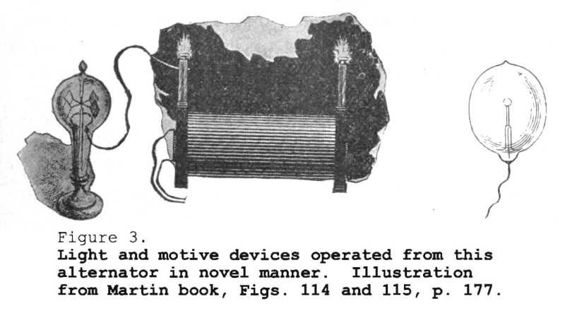
The first result [Fig. 3] was one of the experiments which I at that time showed in a public lecture, motive devices operated by merely connecting them to one terminal of a source of oscillations -- a high frequency coil. I have often been told that my most important results in invention was the demonstration of the practicability of transmitting energy over one wire; because, once we can transmit energy over one wire we can use also the earth, for the earth is equivalent to a large conductor -- a better conductor than copper wire. This was one of the results I got, but the most striking one I will show you now.
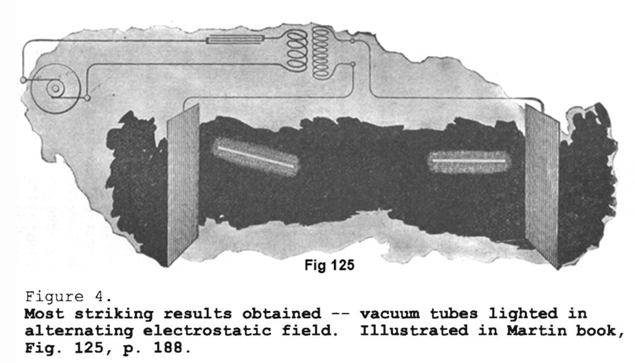
This second result [Fig. 4] shows how energy goes through space without any wire. That was a most striking experiment which was repeated all the world over and was published in thousands and thousands of papers. There is a field produced -- of high frequency -- and in this field I hold two tubes of glass in my hands. These glass tubes spring into powerful light. That was an experiment which carried the whole world by storm; but to me it was the first evidence that I was conveying energy to a distance, and it was a tremendous spur to my imagination and to my energy to develop what I had started.
II. Experiments with Wireless Telegraphy and Telephony
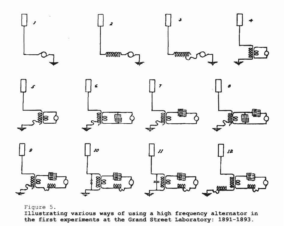
Now, I found that notwithstanding I tuned this system successfully, I could not get this antenna or these "cans," as we called them at that time, charged sufficiently high. But it occurred to me that if I transformed the current and raised the tension of the dynamo in a transformer, I could then charge the antenna to a higher potential and produce a greater displacement of electricity. That resulted in an arrangement like this [Diag. 4 of Fig 5], in which I have the dynamo supply a primary coil, generate a second current of higher potential, and tune the secondary and adjust the conditions so that this conductor [connecting the antenna to the transformer], including the secondary of the coil, is again tuned to the frequency of the dynamo. That was a fine advance; it is the one step that today is absolutely essential, because only in the fewest instances can the power of a generator be taken up without transformation.
Then, of course, I introduced for convenience the improvement [an adjustable coil, shown in Diag. 5, Fig. 5]. That was the fifth step.
In order to increase the current in the primary, I adopted an auxiliary condenser circuit [shown in Diag. 6, Fig. 5]. This auxiliary circuit I have, by the way, already illustrated in a patent which was granted to me in 1891 [U.S. Pat. No. 454,622]. The condenser has the effect of magnifying very much the current, this magnification being proportionate to the ratio of the inductance to the resistance of the circuit, and that ratio was very great so I got a strong current which enabled me to greatly magnify the current in the antenna.
In the next step [Diag. 7, Fig. 5], I have again modified something, but it was not drawn up right. [*3] I put a condenser in series with the primary. That is exactly the way I operated at Columbia College. At Columbia College I had an adustable condenser, purchased from W. Marshall, with very small divisions, which I used in series with an inductance coil, and the secondary I was then operating exhibited all the phenomena which have been described in the lecture.
In [Diag. 8, Fig. 5] I show another modification which has certain virtues. I introduced adjustable condensers here, with which I could, first, counteract the self-inductance of the dynamo in one circuit, then raise the tension in the resonant primary circuit, and then tune the secondary of the system to the same vibration.
In [Diag. 9, Fig. 5], as you see, I came to this arrangement where I have an adjustable inductance and adjustable condenser in the primary, and an adjustable coil in the secondary or antenna circuit. That is now a perfectly common arrangement, and it is very convenient and practical.
In the meantime, as I was developing all this, I had already struck a new line of effort toward producing vibrations; namely, I had developed a system permitting me to take the ordinary current of any main and transform it into any kind of vibrations I desired, either damped or undamped. I will dwell on this [later], but I want to say now that I also operated an arrangement as shown here [Diag. 10, Fig. 5]. I bridged the secondary with an air gap. This I did in studying harmonics. I found that sometimes I could get a very strong harmonic, particularly, for instance, the third harmonic was often very strong. By this arrangement I could work with the fundamental tone and with a harmonic, and I made some interesting observations which later on led me to very important inventions.
[Diag. 11, Fig. 5] is a similar disposition in which I introduced an adjustable condenser, and had the same arrangement in the primary.
And finally, [Diag. 12, Fig. 5] is one of the most common plans which I have been using later in other laboratories - an adjustable inductance in the antenna circuit, and an adjustable condenser and adjustable inductance in the primary circuit.
Counsel
Will you describe, Mr. Tesla, just how far these went into use, and how far they were shown and exhibited to others?
Tesla
At the time I operated in [my laboratory on] Grand Street, I had in my employ the following men: Mr. Anthony Szigety, a practical Hungarian electrician and wire man who had been a long time employed in France and came over in 1884 or 1885, I do not recall now. Then there was Mr. F.W. Clark, a very skilled mechanic, formerly in the employ of Brown & Sharpe. Besides these were Mr. Chareles Leonhardt, a young Hungarian mechanic, and Mr. Paul Noyes, a former employee of the Gordon Press Works of Rahway where I engaged him while I was developing my arc light system, which was adopted by the city at the time. There was also a man by the name of David Hiergesell, a German-American glass blower.
At the time I made these experiments, there were very few of the electricans that since made a success with wireless in some way or another, who would have known much about these things anyway. They had seen me run the wire up the building, they had seen me operate continuously with those machines. I had shown them wonderful results, and had told them all the time that I was going to transmit energy without wire -- telephone, telegraph, run cars and lights at any distance -- and that these were the primary steps toward this end. How much these men could tell, in the light of the present knowledge, that, of course, I am unable to say; but, certainly, I had plenty of witnesses to follow my work and to know what I had been doing.
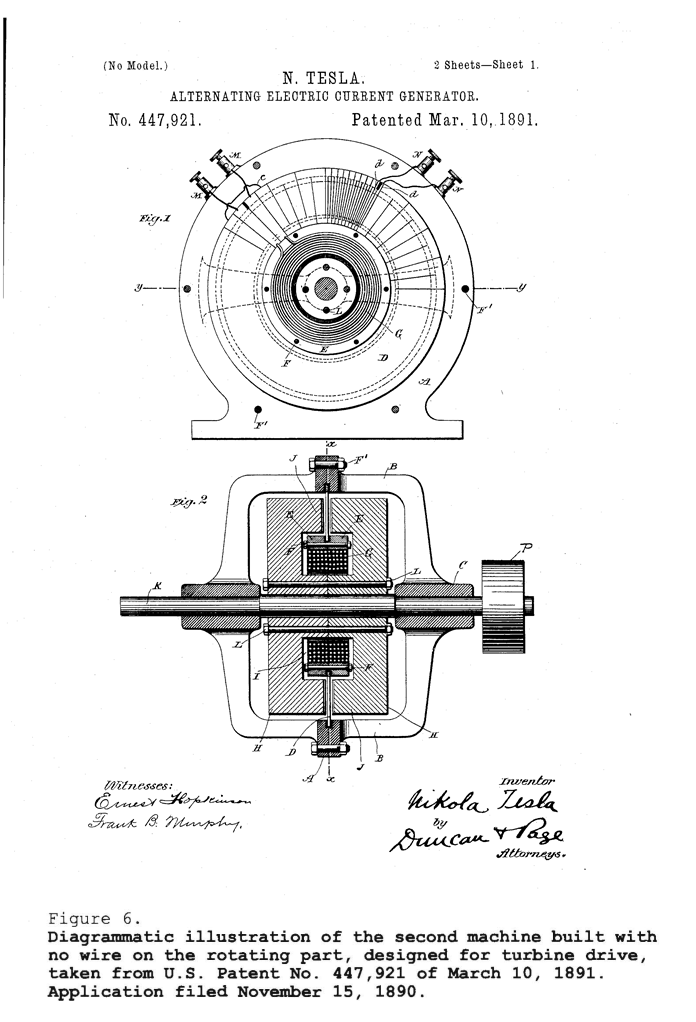
This second machine [Fig. 6] I was building while I was carrying on experiments with first machine. As you will note, I had stripped all the wire from the armature. I had taken the finest steel I could get and constructed a machine with opposite poles, with what we call a "stiff" field, and had done away with all moving wire. I intended to connect a turbine and run this machine at a very high speed, which I thought might be up to 20,000 revolutions. The armature conductors were disposed in this field, and the coil that was exciting the magnet was supported by the conductors, and, as seen in this drawing, I had two wires for the field and two wires for the conductors. Usually, however, I had six binding posts because I had two circuits displaced by quarter-phase in the armature.
I have spent years and years in designing machines, and I have never yet built one machine but that the people who saw it complimented me on its compactness and the thoroughness of my design. These men were students; they did not know how to do it. They made a machine which had an internal resistance of 6 ohms and expected to raise the tension one hundred fold. Why, the resistance of my machine was 1/40 of an ohm only! They wanted to make a short conductor and made a conductor many feet long. The wire in my machine was but 4 feet long. So, you see, I had embodied in this machine the finest thoughts of design. It could not be improved any more because I had gone to the limit of everything; limit of tensile strength , limit of air space, limit of copper, limit of every other material. This machine I have used for many years with great success, and I have discovered many, many facts in connection with wireless by its means, and some of these facts I will tell you.
Counsel
What has happened to that machine?
Tesla
I used it for years and years; used it until recently. That machine must still be in existence, but with the only difference that I have reduced the number of poles. It was to do away with the spark gap. That was an idea that I conceived sometime in 1892, but it dragged on until a later period. My idea was to construct a machine with a certain small number of poles, rotate it at an enormous speed, and thus generate sudden impulses which would produce the same effect as the arc discharge in my so-called "Tesla transformer." Originally, this machine had 64 poles. Then [in 1901] I reduced them to 32, and finally to 16, and that form I have produced with it any oscillations, continuous trains or undamped oscillations of any frequency I desired. That is done by a process not yet well known, except only so far that electricians have produced higher harmonics from low fundamentals; but in that case they have obtained a very small energy. Now, I have perfected a scheme enabling me to take, for instance, this machine, which will give me 3,000 or 4,000 oscillations, and from these oscillations develop 100,000 [oscillations], and there will be a continuous train of undamped waves.
Counsel
During what years was this machine used?
Tesla
This machine was built in 1891. I used it continuously, certainly, until 1905 or 1906.
Counsel
When was it you reduced the number of poles?
Tesla
I reduced the number of poles, I think, in 1901. But then I reduced it for the purpose of generating currents of higher frequency. If I had a great number of poles, I could not realize my idea, because these poles would come in quick succession and not produce a rate of change comparable to the rate of change that is obtainable by the discharge of a condenser owing to a sudden break of the dielectric. That is to say, a blow. It has to be a blow, you see. I had to place my poles comparatively far apart, then run them at excessive speed and generate comparatively few impulses, but each of those impulses are of such tremendous intensity that the dynamo is practically short-circuited. That gave me a blow which replaced the arc. And then, of course, there remained to be perfected a scheme enabling me to get the energy of the alternator in the most economical manner, in high harmonics. That is not known, at least I have not seen anything of that kind in literature, and I believe that if anybody would attempt it without the devices which I have invented, he could not get much of the energy in high harmonics.
Counsel
What was the output of the machine in its original form?
Tesla
The output of the machine was about 8 kilowatts; but, observe, I did not [then] have the turbine [patented in 1913]. If I had had the turbine, I could have run this machine [at] 20,000 revolutions, and then I would have had a [significantly higher] output.
[The machine] had a stationary armature and no wire. It was of the finest steel, all stationary, and the current was taken from the stationary terminals. [It] is the final type which after all these years, other electricians have come to.
Counsel
How fast did you run that before you reduced the number of poles?
Tesla
Up to 12,000 [revolutions]. I used this machine in transmission of signals, particularly with the telephone, in a great many investigations, and I discovered a way, for instance, of measuring accurately capacities employing this machine. You know that, normally, the capacity of an antenna cannot be measured very closely. The ablest men [in the art] -- Prof. Zenneck and Prof. Stone -- know how it is. But, with the scheme I have developed, I could measure any capacity. With an antenna of 1,000 centimeters, I can very easily read half a centimeter. [*4] There is no method known which would enable an expert to read as closely as that. I used this machine in experiments as these. It was a very fine of apparatus for all sorts of wireless demonstrations.
In those years, of course, I was developing the principals. I have shown that five steps had to be accomplished before wireless was an art, a real art that could be applied scientifically.
[Fig. 7] shows this machine as it actually was. You notice here a wire [pointing to the top] -- a solid, thick wire. In the form that you see the machine here, I used it for developing harmonics, and in this case I had a condenser soldered to the alternator so that I would get a system of no resistance, practically. The resistance in my alternator was only 1/40 of an ohm. I made a primary -- that is not seen here -- the resistance of which was also negligible. I combined it with the condenser and tuned it so that I got a current of tremendous volume in that circuit, and then I operated it with the secondary.
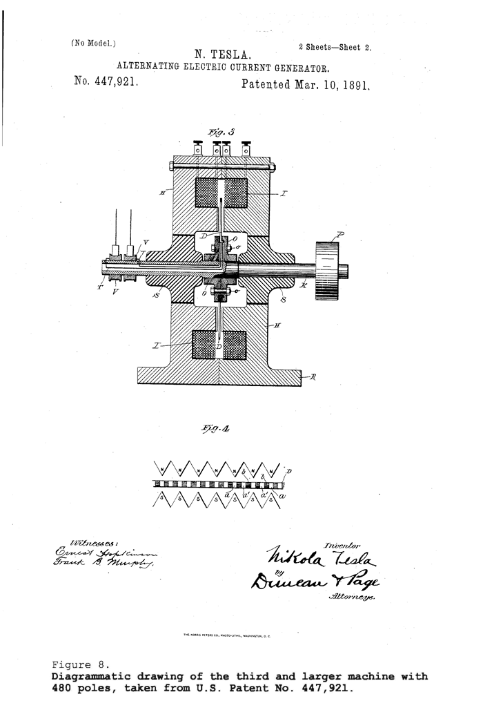
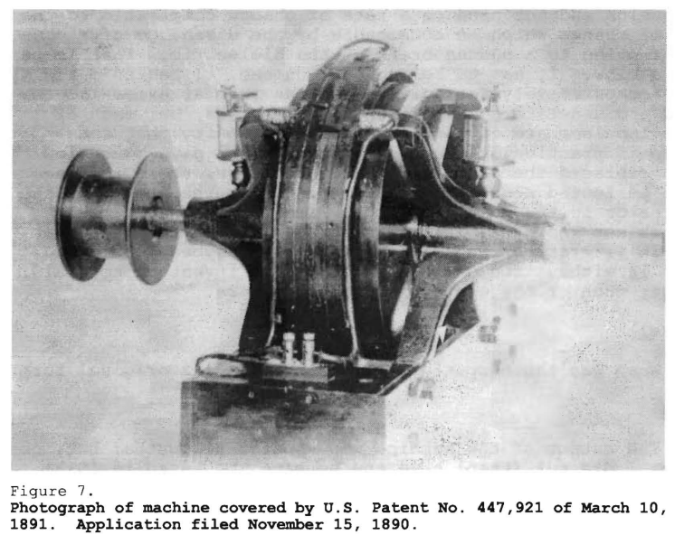
[Fig. 8 shows] another machine. This is the third machine which I built, a larger one. This machine is described by me in the U.S. Patent No. 447,921 of March 10, 1891. It was constructed early in 1891.
U.S. Patent 447,920
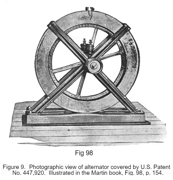
[Fig. 9] is a photographic representation of the machine, but it is not so apparent that it was a machine of much larger capacity. I could get out if it readily 25 kilowatts.
Those are not the only machines I built. I constructed quite a number of other high frequency machines. Some of these were obviously small, and I built them chiefly for scientific investigations and for use in connection with receiving circuits.
One of my ideas was to generate at the receiving station oscillations of a certain frequency, and then combine them with an incoming oscillation to obtain beats. And later on, in 1898, I worked this idea into an invention which has been called a "telautomaton," and which has begun to be appreciated because Congress voted a certain expenditure of money, $750,000, for that machine which I vainly attempted to persuade them to accept. [*5] I perfected the machine in 1898, and tried everything in my power to have it adopted; but, everybody was ridiculing my efforts. Everybody said it is impracticable, and after my patent expired only a few months ago, Congress appropriated this sum and I have now the pleasure of simply looking on when others are using my inventions, which I could not persuade people to adopt. This is usually so.
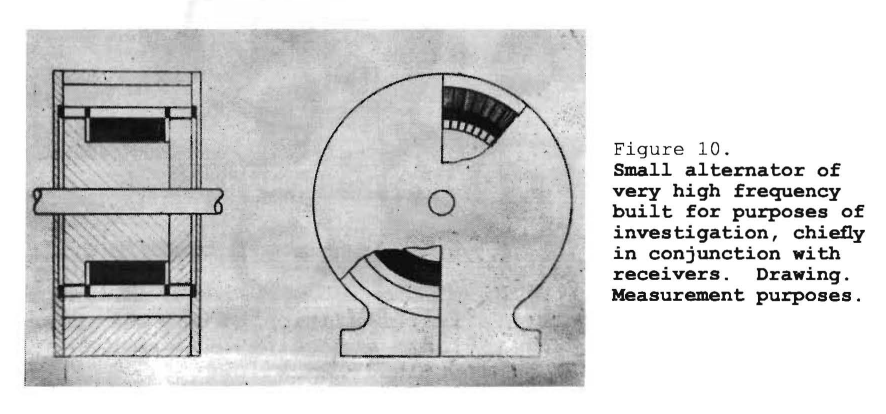
[Fig. 10] shows a type of small alternator, one of two forms which I will show you, that from the constructive point of view, is rather poor. I will admit that. But, it was convenient for me to construct it that way. You see, the magnetic circuit is constituted by the laminated core here, [and] there is an exciting coil. In this picture you will also note the field wires, and the rotor is indicated. With this machine I could get 200,000 cycles per second, [*] very readily, but the output was very small. It was used mostly for telephonic work and for scientific investigations.
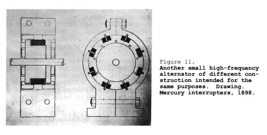
This [Fig. 11], if you please, is another small machine which I built, and with it I also obtained a very high number of cycles. You see how that was made. Here [field] I have 8 laminated magnets, and the circuit was formed through here, you see. On the rotating part I had 9 projections so that if, for instance, this armature was rotated, say, in the clockwise direction, then the magnets will come successively into play also in the clockwise direction. [*] But, as you will readily note, I had a very small electromotive force, for the reason that there was always the inductance of seven coils while one was generating the electromotive force. However, [the] inductance I could overcome resonance, in properly adjusting the capacity, so that was no objection, and the machine was extremely serviceable. This machine gives, by one revolution, 72 impulses -- 72 cycles, because there are 8 poles and 9 projections. That means 8 x 9 = 72. And of course, being small, light, and balanced, I could rotate it a very great speed and get a very high frequency.
Counsel
In what patent was that shown?
Tesla
This idea was disclosed in my patents on mercury interrupters which were published in 1898. You will find the same idea in my mercury interrupters. I use 7 streams of mercury, and 8 projections. In fact, in one I have constructed, I used 25 projections and 24 streams, and I could get a very high frequency which is unobtainable with a very high frequency dynamo.
The machines which I have described so far were all of the ordinary type; that is, insofar as the mode of field excitation was concerned.
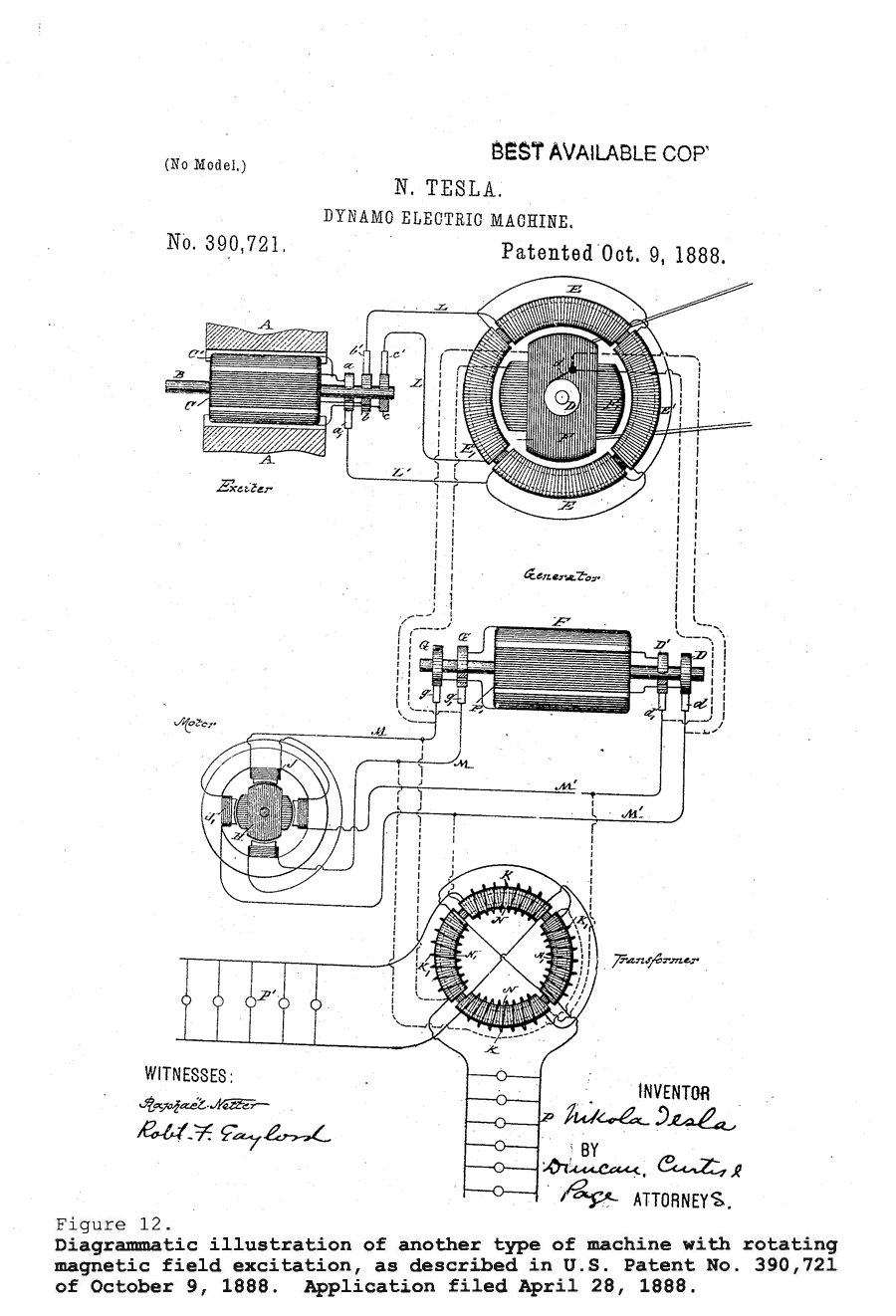
[Fig. 12] shows another type of machine which was patented by me before I had conceived the principal of excitng a machine, not by direct current, but by current of different phase producing a whirling magnetic field, and then rotating the that field an armature and generating currents in the same. This type has been taken up later by a very able German engineer, Mr. Goldschmidt, and today it is known as the Goldschmidt machine. Of course, nobody mentions me at all, and I suppose everything is fair in love and war. But, I gave the idea of these machines, and I has several of them with which I experimented continuously.
There is this to be said [about this type of machine]. When you rotate the armature in the direction of the rotating poles, but with a higher velocity, then it is a machine which has got the field excited by a simple alternating current; when you rotate it in the other direction, then the rotating field really comes in, and you obtain a higher frequency. If you rotate the field just as fast one way as the armature is rotated the other way, you have then, for example, twice the frequency.
The objection to this machine I found to lie in the fact that the current is not strictly sinusoidal. You see, when the flux in the field varies harmonically there are two inductions; one is the induction due to the motion of the wire across the field and the other is the induction comparable to that taking place in a static transformer. This latter is porportional to the sine, the other is porportional to the square of the sine, and the result is that we get a little distorted curve. Nevertheless, the principal is applicable, and [it] has been applied by Goldschmidt in a commercial machine.
Now I am coming to a very wonderful discovery which I made in connection with high frequency alternators, and I do not believe that there is a man in the technical profession today who dreams about it; not one. This discovery proved to me that, without further provision, it was impossible to use a high frequency alternator in wireless work that required any kind fineness; and I made this discovery in the following way. I was operating with three high frequency alternators in my laboratory at 35 South Fifth Avenue. I would run [any] one of the machines, tune a circuit, then go around the city and get the hum of the alternator in my tuned receiving circuit, and from this note and the intensity of sound I could judge the quality of the devices that I was using. That was a very convenient way; I did it continuously. I operated mostly between the laboratory on South Fifth Avenue and the Hotel Gerlach on 27th Street, near Sixth Avenue, where I was stopping.
While I was carrying on this work I was perfecting methods and apparatus for attunement, and I noticed that gradually I could not get as good results as I got before. I could not understand this. But after a few days of investation, one day it happened that I was trying to get a note on the top of the Gerlach and could not get the hum of the alternator. I was giving it up, when all of a sudden out it rang very sharp and clear, and was off again suddenly, as though a wire had been broken. I said to myself, a wire has been broken somewhere in the circuit and went down to the laboratory where I examined all carefully. But everything was in order. Then the idea flashed upon me that my receiving circuit was sharply attuned, and the alternator was all the time changing speed, like every alternator does. It does not give one frequency, it gives many frequencies.
Now, I solved that problem in 1898, and I will tell you how I solved it. I said to myself, here is a generator that gives a dozen different frequencies, but very closely related. They follow one another in succession. How am I going to get selectivity, and at the same time have a perfect response? I solved this through what I term the principle of individualization. An ordinary circuit has one characteristic; it responds to a certain note. An individual has more than one characteristic; [he] comprises many in combination. Similarly, I combine several circuits and depend on the cooperation of these circuits to operate my device.
My first step was to tune several circuits very closely together, so closely that they would pick up [any] of the frequencies within the range of the change of the alternator [speed], and I operated with all these circuits on my receiver. The moment I used that kind of a circuit, I found that I got very clearly the note of the alternator because my receiver was responding to any of the frequencies which were produced. On the other hand, when foreign frequencies would come in to disturb, I would only get a partial effect, as my normal effect was due to all the frequencies combined, whereas the outside effect was due to just the one frequency. I presented the same principle in a lecture before the New York Academy of Sciences on April 6, 1897, but which was not published.
There were certain steps to be accomplished, [however,] before the wireless could be on a really practical and scientific basis. The next step to accomplish, after all had been done, was to design an apparatus which will exactly suit the earth; that is, which will give the proper wavelengths suitable for it, and will also be in all other respects adapted to the physical conditions of the globe on which we live, and to the place on which the plant is erected. The earth is not a sphere; it is an oblate spheroid, owing to the effect of centrifugal force. Now, it makes all the difference whether a scientifically correct apparatus is placed in a northern region, near the pole, or near the equator, because the length of the conductor is not the same.
In the account of the experiments and machines which I [have earlier shown], I hope I have proved that those machines represented the farthest advancement in the art, not only of that time but of the present day. Not that I would say I was a better designer -- nothing would be further from my mind. I simply mean that my followers did not require the limitations of frequency, and I have stuck to those designs which were most efficient. Alexanderson said,
"We are compelled to go to the very frequencies that you [i.e., Tesla] used in your earlier demonstrations."
There were reasons why I made machines of low frequencyin my experimental work, why I stuck to these frequencies which I have used in my early lectures and public demonstrations. Firstly, because such a machine can be efficiently built for high output, which a machine for 200,000 cannot. Secondly, the waves which are generated were less absorbed because they are of lower frequency. They went to greater distance; the effects were greater. But there was still a third reason: Whenever I received the effects of a transmitter, one of the most convenient and simplest ways [to detect them] was to apply a magnetic field to currents generated in a conductor, and when I did so, the low frequency gave audible notes.
Note: I wish they would stop calling Tesla's system "radio". It's not radio. Tesla designed his transmission circuits to be non-radiative. He goes on at length, repeatedly, stating that his system of transmission of energy, whether the transmission of energy is for things like lights and motors, or for communications applications like telegraph, telephony, or ticker tape machines: all operated on non-radiative (NOT radio) transmission modes. Tesla deliberately kept his frequencies too low to radiate efficiently, sometimes he applied one terminal of a capacitor to the top of a transmitter configuration, where the conductive air terminal would be. The air terminal in all but the most powerful transmitters is neither radiating energy out into space, nor conducting energy off into the atmosphere. Tesla transmitters and receivers all conduct their respective signals into/onto the ground. The ground for many miles near even a small Tesla transmitter is literally vibrating at audio frequency rates. When you ground your receiver, the receiving circuit vibrates in sympathy with the ground wave vibration injected by the transmitter. Tesla must have looked quite the sight... He carried lighter than air balloons, coated with thin conductive foil, from his laboratory building to the roof of the Hotel Gerlach. He connected the conductive balloons to the air terminal of the receiving coil in the above photographed device. But the balloons were not picking up any signal. Tesla found a water pipe that ran all the way to the hotel rooftop. The water pipe carried the signal. The balloons simply acted as a capacitance, making it easier for the signal picked up from the water pipe to pass as a current through the receiver coil. Tesla also used Leyden jars in place of balloons or other air terminals. And he had large metal "cans", as they were called in his laboratory, mounted on the building roof on insulated standoffs. Tesla ran wires from the lab up to the roof to connect to one or more "cans" or open ended capacitors. In Fig 125 in the Martin book, Tesla used metal plates. I do find instances in the historical record of Tesla operating well into the radio range, he talks about the techniques he used to reach these frequencies in this deposition, but between problems with frequency stability, and energy loss to radiation, Tesla went back to lower frequencies and a conductive, cymatically excited, transmission mode. Now back to your regularly scheduled program:
One of the simplest devices I used in my experiments between my laboratory on South Fifth Avenue and [at] the Gerlach Hotel, and other places in and outside the city, was an instrument constructed in 1896 with a magnet which sometimes was so designed as to give me a very intense magnetic field up to 20,000 lines per square centimeter. In this [field] I placed a conductor, a wire or a coil, and then I would get a note which I amplified and intensified in many ways. From the characteristics of the audible note, I would immediately judge the quality of my apparatus.
When I speak of an audible note, I mean a note audible in a telephone as produced by the diaphragm of a telephone, or by a vibrating wire within the range of audibility.
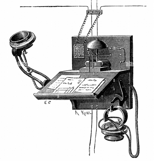
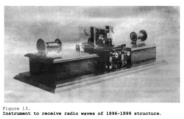
[Fig. 13] shows the general arrangement of [the receiving] apparatus. [*] Two condensers are the boxes at each end, and in the center a coil, or two coils, according to necessity, with which I produced a strong magnetic field and [placed] in it a wire. These condensers and the wire form a circuit which I tune. The condensers are of comparatively large capacity because my conductor is so short. I usually would transform the current in the receiving circuit and make as close a connection as possible and then tune the circuit to the vibrations. I would also mechanically tune the wire, according to the frequency, to the same note or to a fundamental.
This machine was suitable for transportation. I could put it under my arm with a couple of batteries. I had relays, which were very big, in which I produced (for stationary work) a very intense magnetic field so as to affect the conductor by the feeblest current. Furthermore, I used these relays particularly in connection with beats. When the frequencies were very high, I combined two frequencies very nearly alike. That gave me a low beat. One of the frequencies I sometimes produced at the receiving station, and at other times at both the receiving and transmitting stations. This always gave me the means of producing an audible note. I used machines of this character from 1892, but this specific instrument in my laboratory on Houston Street.
This instrument comprising a magnet and chord or coil in the magnetic field -- I mean a wire or coil in the magnetic field -- is an old academic device, used in all sorts of demonstrations at the schools and the university where I was studying. My professor of physics has had similar instruments with an adjustable spring and magnet, and I have employed them in assisting him. There is nothing novel in the idea. The only novelty was that I kept my alternation low and I made this arrangement with conductors to tune.
It was very convenient for producing audible effects because, if I used other forms of a receiver, I had a reading which was not at once translatable. If I listened to a note, I could immediately tell the quality of the transmission. For instance, I would tune a circuit in my laboratory, take it out to another building, and I would receive the signals; and from the quality of the signals I would see how I was progressing.
Counsel
In the experiments that you have spoken of with the instrument of which the picture is shown [as Fig. 13], what were the distances between the transmitting and receiving stations?
Tesla
The distance at that time, and I think the greatest distance at which I ever received signals from the Houston Street laboratory, was from the Houston laboratory to West Point. That is, I think, a distance of about 30 miles. This was prior to 1897 when Lord Kelvin came to my laboratory. In 1898 I made certain demonstrations before the Examiner-in-Chief of the Patent Office, Mr. Seeley, and it was upon showing him the practicality of the transmission that patents were granted to me.
Counsel
At that experiment were you at the Houston Street end or at the West Point end?
Tesla
In that experiment I produced continuous trains of oscillations and went with the instrument to West Point. I did this two or three times. There were no signals actually given. I simply got the note, that was for me just the same.
Counsel
That is to say, you did not make and break the circuit?
Tesla
No, and I did not receive any signals, but I did receive the audible notes in my telephone receiver.
Counsel
At West Point?
Tesla
Yes, in or about the year 1897.
Counsel
And did the continuous transmission thus received start from Houston Street?
Tesla
Yes
Counsel
Was one of your employees there?
Tesla
Yes, the employees knew that I was running the apparatus. On frequent occasions I would get a boy to make and break the circuit. Then I found it was much simpler to just let the apparatus run and get the notes.
Counsel
What was the distance between transmission and reception?
Tesla
That was the distance from my laboratory on Houston Street to the Gerlach Hotel.
Counsel
Is this instrument [Fig. 13] the same general type which is colloquially known as a string galvanometer?
Tesla
No, it is not. Such a scientific instrument is used in the schools, for instance, in various kinds of demonstrations.
Counsel
In [Fig. 13], is that [wire] shown on the apparatus in series with the circuit, and is it in the field of the magnet?
Tesla
Yes. I had a coil, or a straight wire, in the field -- it made no difference. It was the reaction of the currents on the field that produced the audible note.
Counsel
What is the furthest distance from your source of transmission that you used the apparatus of this character?
Tesla
I think that I used this once at the Western Union Building -- on the roof -- in company with Mr. Alfred K. Brown. That would be a distance of probably 2 miles.
Counsel
What was the character of the reception?
Tesla
Just the alternator was run and you could hear the note of the same when the circuit and the string was tuned to the same frequency.
Counsel
Did you hear it?
Tesla
You could hear it all over the place.
Counsel
You mean you did not have to have your ear in the telephone to hear it?
Tesla
No, not at all; I could hear it from a distance. The vibrations were very vigorous.
Counsel
About when was that?
Tesla
That must have been either late 1886 or early 1887.
Counsel
What was the frequency of alternation that you were using?
Tesla
The frequency might have been something like -- I should say - in the neighborhood of 5,000.
Counsel
Was there anything hidden about these uses, or were they open so that anyone could use them?
Tesla
There were thousands of people, distinguished men of all kinds, from kings and greatest artists and scientists in the world, down to some old chums of mine -- mechanics, to whom my laboratory was always open. I showed it to everybody; I talked freely about it.
Counsel
When you said, "5,000," did you mean cycles or alternations?
Tesla
I mean cycles. On another occasion I have also operated going a little further into showing the reactions of high frequency currents upon magnetic fields -- I have operated motors, and at that time I have stated what frequencies had to be used in order to produce these rotations, which are, of course, due to reactions of the currents on the field. I have pointed out, in the Martin book, that they should be from 5,000 to 10,000.
I would like to proceed, without going into details making this too hard to follow. I would like to have this simply a clean story with only the salient facts pointed out, and not a maze of little details which would complicate it and spoil the harmony. Proceeding, then,
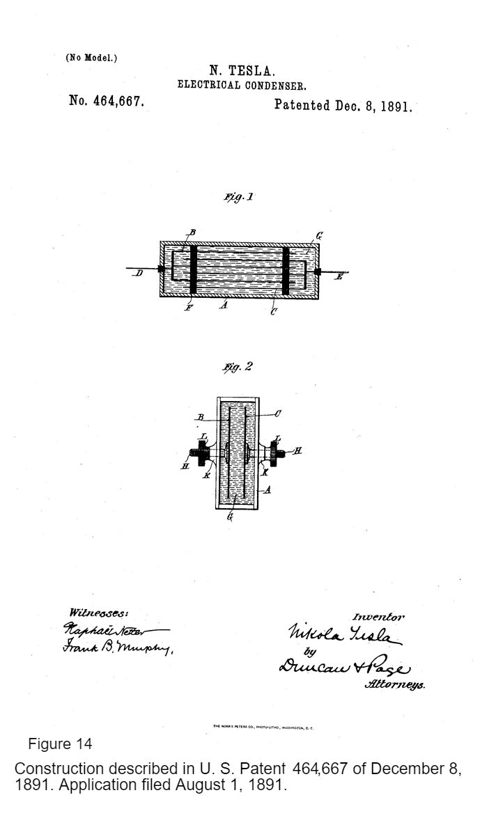
[Fig. 14] shows a form of condenser in which I have boiled out all the air bubbles, and the next drawing
[Fig. 15] shows another form.
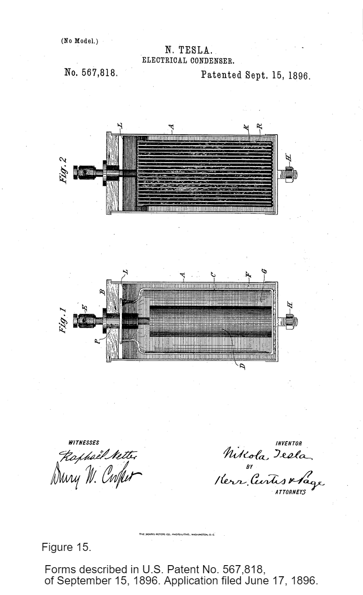
I have made a notable advance in this condenser, with which I have operated in my laboratory on Houston Street and in experiments at my wireless station in Colorado. This is the most efficient form of condenser known, showing practically no loss whatever. And it is only with this condenser that really very fine results are obtainable because, even if we employ mica condensers immersed in oil, or glass of the best kind coated with tinfoil, we do not get the results which we get with this condenser, and they are obtained by substituting electrolyte for the metallic coatings as before. I used electrolytes which were especially adapted for that, and cheap -- for instance, like a solution of ordinary salt. It is cheap and readily obtainable.
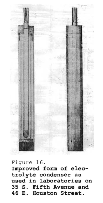
[Fig. 16] shows a type of this kind of condenser in finished form as I used them in my laboratories. There were many of these adapted to be secured on the bottom. They were readily transportable. Occasionally, I took some of these condensers with me when I experimented.
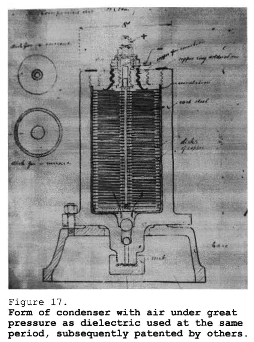
[Fig. 17] shows another improved form of condenser. I do not have a photograph of a finished apparatus and this is a sketch that was made in 1896 shortly before a condenser of this kind was constructed. That was a condenser intended for high electric pressure and the insulation was obtained through the air. It was built for 500 atmospheres air pressure safely. There is a reference in my writings where I point out the use of compressed air, and therefore there was no creative effort involved in any patent in that direction by Fessenden and others.
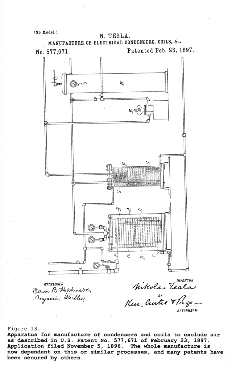
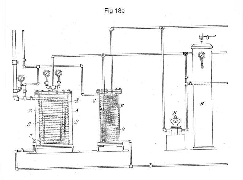
The apparatus shown by the drawing [Fig. 18] which I designed and installed was for years employed to practice this process of manufacture. This process is [now] universally adopted; everybody uses it. There are millions and millions involved in it. If I could only get one cent for every apparatus that is manufactured in accordance with my invention, I could erect a building like the Woolworth and not feel the expense. [*] Everybody uses it, but nobody says thanks. That was arranged for what was called a vacuum pressure process.
Steinmetz says, "No, I have found a better way. I just put the thing in kerosene."
It is thin and penetrates in the inside and, of course, he gets a patent.
III. Mechanical and Electrical Oscillators
I am [next] coming to a chapter in my life which was very fruitful. I was absorbed in the development of a new type of generator. The solution, which enables me to use the high frequency alternator practically, was not yet found at that time. I saw that the high frequency alternator was not usable for any finer work. We were driving toward perfection and that if we attained it, the alternator would be simply thrown away as an absolute useless instrument. That was my conviction, and I attempted to attain the results which I subsequently reached with the alternator in another way. To this end I built a great many machines of a novel type, which I called oscillators -- mechanical and electrical oscillators -[Also See: Cymatics]- and it is with these that my best results in the investigations of these phenomena applicable to wireless in many of its phases, were obtained.
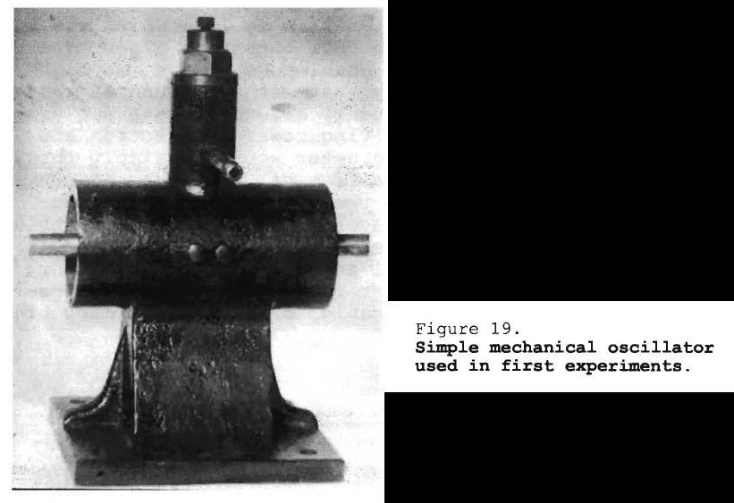
The photograph [Fig. 19] shows my earliest experimental oscillator which I used to generate electrical vibrations.
My first efforts were to produce this vibratory mechanical motion, then attach to this system an electrical generator; that is, I would attach a conductor to it and vibrate it in a magnetic field. That was the first step in the evolution of the idea. The machine is shown here without any attachments.
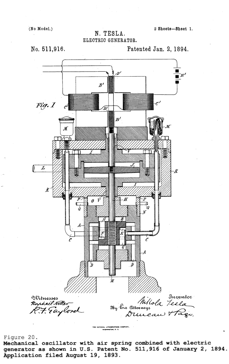
The drawing [Fig. 20] illustrates the next advance in the evolution of the idea. I have produced isochronous oscillation, and now I am applying considerable power to the piston to develop energy in this electric system. It is the energy of the mechanical system which produces the electrical energy in the circuit, but the vibration is controlled by the tremendous force of the air spring against which the small impressed force is nothing. In this manner, then, I first obtained isochronous electrical oscillations, which no transmitter made today furnishes except my own.
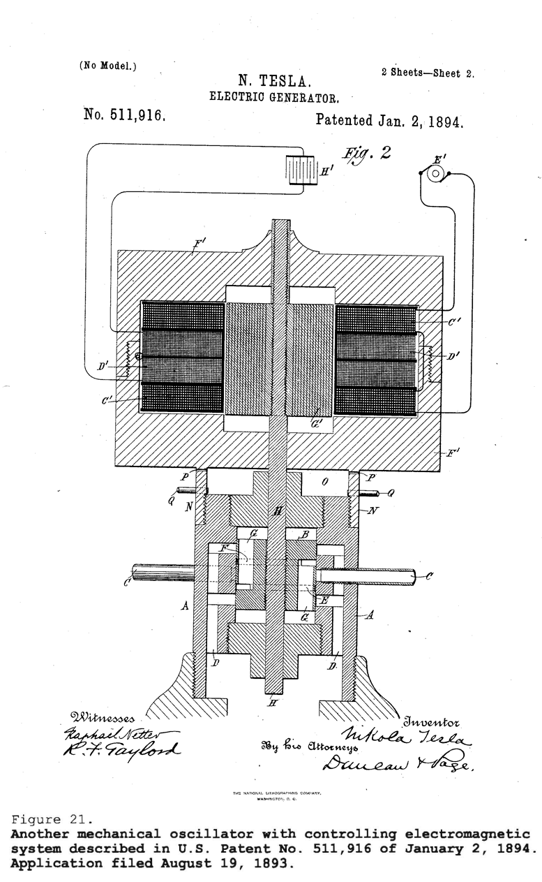
The drawing [Fig. 21] illustrates the next improvement. I conceived the idea, instead of using a mechanical air spring for exercising the controlling force, to obtain it electrically. Boiling water was employed to keep the temperature of the air spring perfectly constant and the oscillations isochronous. I constructed an electromagnetic field so that it could be used for isochronous control. This invention I also exhibited at the Chicago World's Fair where scientific men, Helmholtz and others, saw it. The magnetic field [of the] core generates currents in the coils. Two coils are used for excitation and two for induction. I connect a condenser to the latter and adjust the period of the electromagnetic system, comprising the condenser and the self-inductance, so that it is just suitable for the conditions under which I wish to operate. Then the magnetic system, having a constant period of vibration, controls the admission of the fluid to the piston, and when I use the currents I find them perfectly isochronous. I can run a clock with them and it will show correct time. The vibrations obtained in this way would not vary one millionth of a second in a thousand years.
Click for higher resolution image.
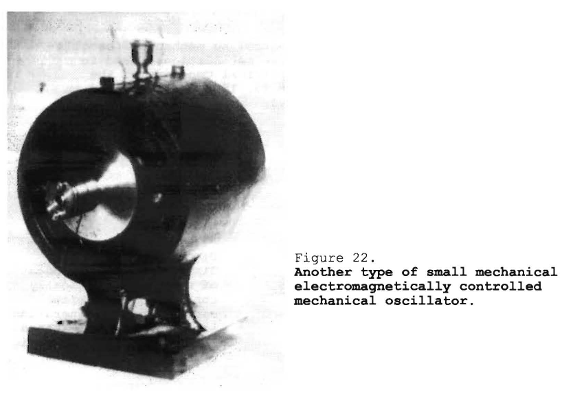
The photograph [Fig. 22] shows another form which I also exhibited at the Chicago World's Fair. There is a round coil, you see, in the field; on the other side is another such coil. I performed very curious experiments with this machine. For instance, among other things, I produced direct currents without commutation.
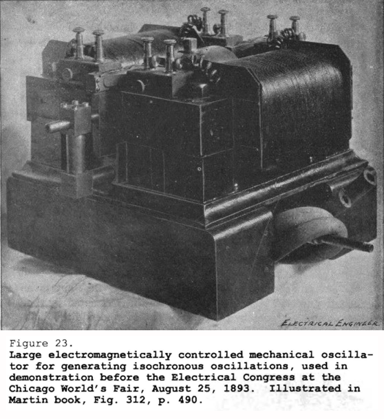
Here [Fig. 23] is, I might say, the first commercial oscillator which I designed and constructed and which was exhibited at the Chicago World's Fair. With this, I also performed many experiments. As you will observe, I have a powerful magnet in two parts for producing a strong field on both sides, and in it are conductors which are vibrated by an engine in the center.
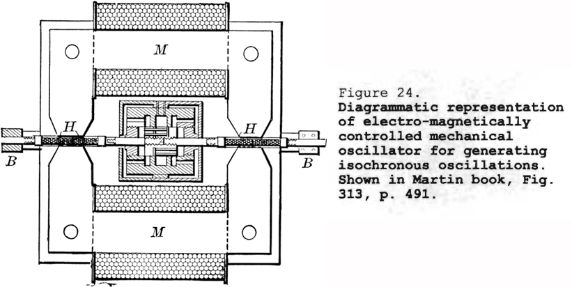
That [Fig. 24], as you see, diagramatically represents the arrangement. Here [at the center] is my little engine, and here [at H and M] are the conductors and the magnets producing a very strong field. I observed very curious phenomena with this machine, which I subsequently turned to great advantage.
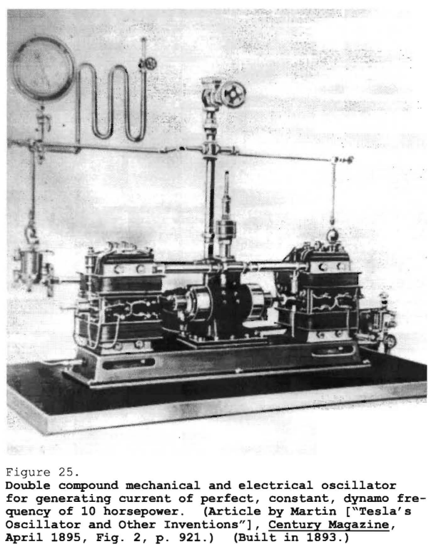
With this one [shown in Fig. 25], I operated normally in my laboratory at 35 South Fifth Avenue. It was primarily installed there. The Babcock and Wilcox people had the kindness of specially constructing a boiler for me which could stand a pressure of 1,000 pounds. This machine was capable of developing up to 10 horsepower. It was, as you see, composed of two magnets or magnetic fields and a compound engine for imparting vibration to the conductors in the fields. It was controlled by an isochronous oscillator and, in addition, I tuned the electromagnetic system when I operated.
Counsel
What frequencies were developed?
Tesla
Those were low frequencies, but I will tell you how I solved the problem of high frequencies.
Counsel
When was that machine developed, Mr. Tesla?
Tesla
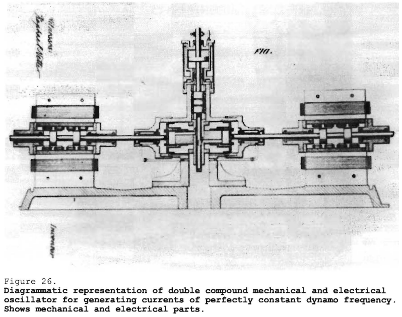
This machine was built in 1893 and was operated until May 1895, when a fire destroyed my laboratory. You will appreciate better this photograph [Fig. 25] if I show this drawing [Fig. 26] that was made for the patent specification at that period.
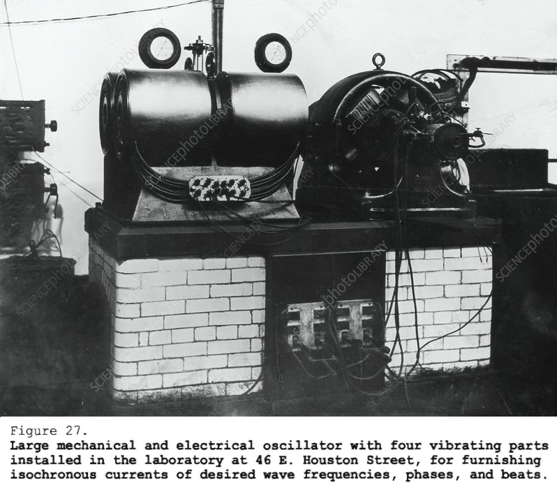
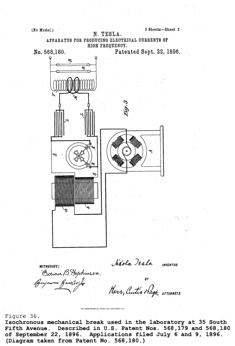
I come now to a large machine which was built in my laboratory on Houston Street. Immediately after the destruction of my laboratory by fire, the first thing I did was to design this oscillator [shown in Fig. 27]. I was still recognizing the absolute necessity of producing isochronous oscillations, and I could not get it with the alternator, so I constructed this machine. That was all a very expensive piece of work. It comprised four engines. Those four engines were put in pairs and there was an isochronous controller in the center, and furthermore, that controller was so arranged that I could set two pairs of engines to any phase or produce any beat I desired. Usually I operated quarter phase; that is, I generated currents of 90° displacement.
By the way, now, for the first time you see my apparatus on Houston Street, which I used for obtaining oscillations, damped and undamped as well. But, it is necessary to state that while others, who had been using my apparatus, but without my experience, have produced with it damped oscillations, my oscillations were almost invariably continuous, or undamped, because my circuits were so designed that they had a very small damping factor. Even if I operated with very low frequencies, I always obtained continuous, or undamped, waves for the reason that I designed my circuits as nonradiative circuits. I will explain that later.
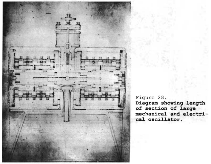
In this diagram [Fig. 28] I show the general arrangement of these engines installed in the laboratory at 46 East Houston Street. There were four, with four vibrating parts installed for furnishing isochronous currents of desired wave frequencies, phases, and beats.
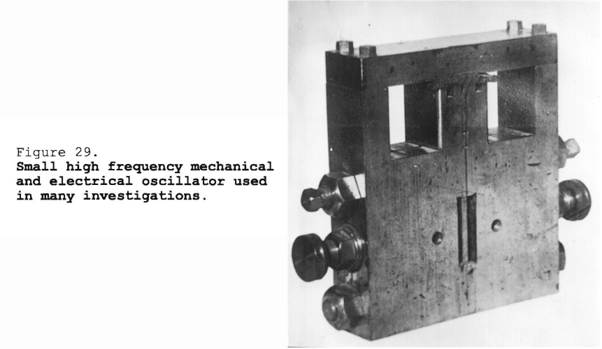
That oscillator [Fig. 29] was one of high frequency for isochronous work, and I used it in many ways. The machine, you see, comprised a magnetic frame. The energizing coil, which is removed, produced a strong magnetic field in this region. I calculated the dimensions of the field to make it as intense as possible. There was a powerful tongue of steel which carried a conductor at the extreme end. When it was vibrated, it generated oscillations in the wire. The tongue was so rigid that a special arrangement was provided for giving it a blow; then it would start, and the air pressure would keep it going. The vibrating mechanical system would fall into synchronism with the electrical, and I would get isochronous currents from it. That was a machine of high frequency that emitted a note about like a mosquito. It was something like 4,000 or 5,000. It gave a pitch nearly that of my alternator of the [first] type which I have described.
Of course this device was not intended for a big output, but simply to give me, when operating in connection with receiving circuits, isochronous currents. The excursions of the tongue were so small that one could not see it oscillate, but when the finger was pressed against it the vibration was felt.
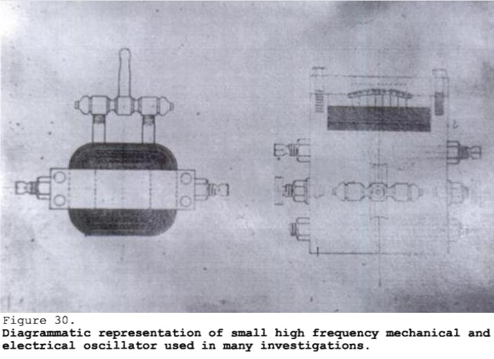
This drawing [Fig. 30] shows the construction in detail. Here is the field coil, here are the conductors in the intense field, the valves for air supply, and the stops for limiting vibration. The stronger the field was excited, the [stronger] the vibrations became, but just the same, while the amplitude changed, the isochronism was not disturbed.
I want to say now why these machines were the means of obtaining the best results in my wireless work. The machine at the Houston Street laboratory with which I could obtain any difference of phase, as well as that machine at 35 South Fifth Avenue, were the means of running a motor in perfect isochronism. That is, if I connected a synchronous motor to these machines and drove it with currents of different phase, I obtained an absolutely uniform rotation -- constant in time -- and when I coupled this motor directly to an alternator, I obtained from the latter currents of absolutely constant frequency, all the more readily as I tuned the circuit of the alternator to the same frequency.
These machines I have described in a general way only. The work has covered years, and it would take a long time to explain all about them. They enabled me to operate in whatever I did with currents of constant frequency, and the small alternators in my experiments were driven this way. While this work was going on, I was perfecting various other ways of generating electric oscillations of absolutely constant frequency which were not then producible in the art.
See: Tesla's Electrical Isochronous Oscillators
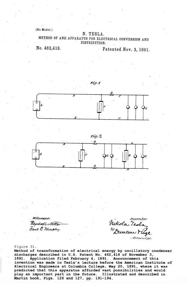
This work [Fig . 31] was begun already in 1889. This type of apparatus is identified with my name as certain as the law of gravitation is with that of Newton. I know that some have claimed that Professor [Elihu] Thomson also invented the so called Tesla coil, but those feeble chirps ne'er went beyond Swampscott. Professor Thomson is an odd sort of man; very ingenious, but he never was a wireless expert; he never could be. Moreover, it is important to realize that this principle is universially employed everywhere. The greatest men of science have told me that this was my best achievement and, in connection with this apparatus [referring to schematics of Fig. 31], I may say that a lot of liberties have been taken. For instance, a man fills this space [break D] with hydrogen; he employs all my instrumentalities, everything that is necessary, but calls it a new wireless system -- the Poulsen arc. I cannot stop it. Another man pus in here [referring to space between self-inductive lines L L] a kind of gap -- he gets a Nobel prize for doing it. My name is not mentioned. Still another man inserts here [conductor B] a mercury[-arc] rectifier. That is my friend [Peter] Cooper Hewitt. But, as a matter of fact, those devices have nothing to do with the performance.
If these men knew what I do, they would not touch my arrangements; they would leave my apparatus as it is. Marconi puts in here [break D] two wheels. I showed only one wheel; he shows two. And he says, "See what happens when the wheels are rotated; a wonderful thing happens!" What is the wonderful thing? Why, when the teeth of the wheels pass one another, the currents are broken and interrupted. That is the wonderful thing that happens? The Lord himself could not make anything else happen unless he broke his own laws. So, in this way, invention has been degraded, debased, prostituted, more in connection with my apparatus than in anything else. Not a vestige of invention as a creative effort is in the thousands of arrangements that you see under the name of other people -- Not a vestige of invention. It is exactly like in car couplings on which 6,000 patents have been taken out; but all the couplings are constructed and operated exactly the same way. The inventive effort involved is about the same as that of which a 30-year-old mule is capable. This is a fact.
This is one of most beautiful things ever produced in the way of apparatus: I take a generator of any kind. With the generator I charge a condenser. Then I discharge the condenser under conditions which result in the production of vibrations. Now, it was known since Lord Kelvin that the condenser discharge would give this vibration, but I perfected my apparatus to such a degree that it became an instrument utilizable in the arts, in a much broader way than Lord Kelvin had contemplated as possible. In fact, years afterwards when Lord Kelvin honored me by presenting to the British Association one of my oscillators of a perfected form, he said that it was "a wonderful development and destined to be of great importance."
[Returning to a discussion of Fig. 31], [E] is supposed to be a condenser. That [A] is the generator. Now then, supposing that this is a generator of steady pressure. I can obtain oscillations of any frequency I desire. I can make them damped or undamped. I can make them of one direction or alternating in direction as I choose. At G are devices which operate -- lamps, or anything else. Some experimenters who have gone after me have found a difficulty. They said,
"No, we cannot produce a constant train of oscillations."
Well, it is not my fault. I never have had the slightest difficulty. I produced constant oscillations and I have described how I produced them. Anyone who has no more than my own skill can do it.
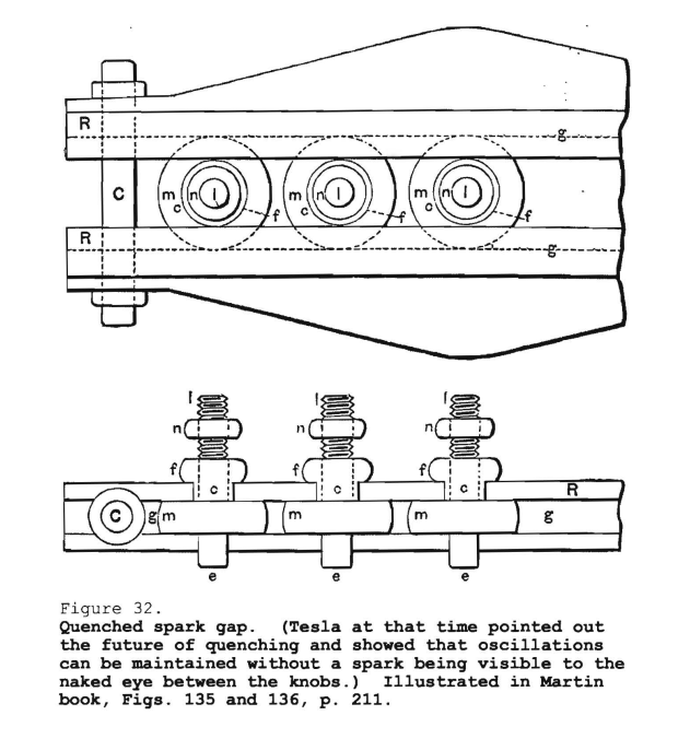
This [Fig. 32] is another improvement in that particular device, which was the weakness of the invention and which I tried to eliminate. This device incorporated many spark gaps in series. It had a peculiar feature; namely, through the great number of gaps, I was able, as I have pointed out in my writings, to produce oscillations without even a spark being visible between the knobs. This device is now known in the art as the "quenched spark gap." Professor Wein has formulated a beautiful theory about it, which I understand has netted him the Nobel prize. Wein's theories are admirable. The only trouble is that he has overlooked one very important fact. It is this: If the apparatus is properly designed and operated, there is no use for the quenched gap, for the oscillations are continuous anyway. The radio men who came after me had the problem before them of making a bell sound, and they immersed it in mercury. Now, you know mercury is heavy. When they struck their bell, the mercury did not permit it to vibrate long because it took away all the energy. I put my bell in a vacuum and make it vibrate for hours. I have designed circuits in connection with an enterprise in 1898 for transmission of energy which, once started, would vibrate three years, and even after that the oscillations could still be detected. Professor Wein's theory is very beautiful, but it really has no practical meaning. It will become useless as soon as the inefficient apparatus of the day, with antennae that radiate energy rapidly, [areJ replaced by a scientifically designed oscillator which does not give out energy except when it gets up to a tremendous electromagnetic momentum.
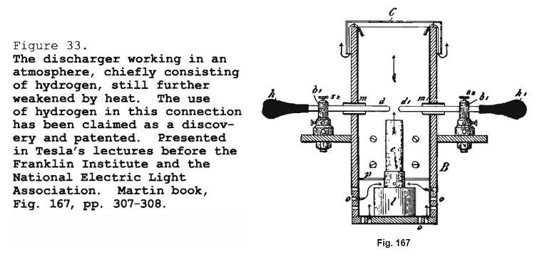
In this form of break [Fig. 33], I changed the atmosphere in which the arc was operating. The atmosphere was mostly hydrogen, and with this device I performed experiments before the Franklin Institute and the National Electric Light Association in St. Louis. This has been used by Poulsen and it is now called the "Poulsen arc" and "Poulsen system." But, of course, there is no invention in it. I am on record with prior publications, and besides, the hydrogen does not have any other effect except that it lowers the tension under which the device can operate. It has the disadvange of producing aysmmetrical or distorted waves, and the impluses obtained are not best suited for tuning.
This [Fig. 34] is the apparatus used in the Chicago Exposition of 1893, at which time I explained for the first time to Professor Helmholtz my plan for transmitting energy. After I had shown Professor Helmholtz and other scientific men there certain phenomena, he asked me,
Now, what is all this intended for?
I told him I was trying to develop an apparatus for transmitting energy without wire for telegraphy, telephony, and other purposes. When I explained to Professor Helmholtz the whole idea I said,
"Excellency, do you think that my plan is realizable?"
He replied,
"Why certainly it is, but first you must produce the apparatus."
I started then and there to produce the apparatus.
Counsel
Was that conversation at the Chicago Exposition?
Tesla
Yes. It took place in a pavilion which was built especially for exhibiting my inventions and discoveries. I believe Professor Wedding was there and some other scientists whom I cannot remember now. I showed Professor Helmholtz my vacuum tubes and performed many other experiments.
Counsel
Will you describe this apparatus in a little more detail?
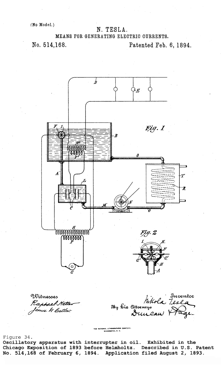
Tesla
The apparatus [Fig. 34], as you see, comprised primary and secondary coils immersed in a large tank of oil. The break was automatically effected by means of a turbine. The oil was circulated by a pump, and the current [i.e., stream flow] of oil drove the turbine which effected the make and break. Owing to the fact that the oil used was a very good insulator, rapidly flowing and of great dielectric strength, these make-and-break points were very close together, and the arcs extremely short. The effects were accordingly more intense. Here [T in Diag. 1 of Fig. 34] is a cooler through which the oil was circulated. The oil was forced through the gaps at great speed, and as it flowed out it was supplied again to the tank and the current driving the turbine.
Counsel
That device [Diag. 2 of Fig. 34] you call a turbine?
Tesla
Yes. It had vanes like those of a propeller and constituted a rotary break in the circuit.
Counsel
What was your prime source [of power]?
Tesla
The primary source was an alternator with a frequency of 133 cycles and, if I recollect rightly, the pressure [at the secondary] was about 20,000 volts. I may have had 10,000 volts. I am not sure what it was, but it must have been certainly from 10,000 to 20,000 volts -- within that range.
Counsel
I notice you have two sets of transformers in there marked S and S', have you not?
Tesla
This [S'] is my oscillatory circuit. That [S] is the transformer from which the condenser was charged. Here [at S] we had 20,000 volts, or whatever it was, from the commercial transformer and here [at S'] is my secondary which generated the high frequency currents. The rotary gap is shown in detail [Diag. 2 of Fig. 34].
I had a special reason for showing this. To meet that great man Helmholtz and other scientific men, and to bring before them for the first time the results of years of previous labor, was an important moment in my life -- particularly because Professor Helmholtz gave me the assurance himself that what I explained to him was realizable, provided that I could produce the apparatus. I was very much encouraged
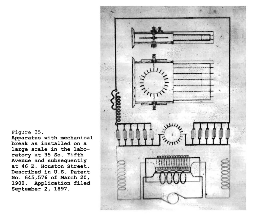
This [Fig. 35] is the apparatus I had at 35 South Fifth Avenue and also Houston Street. It shows the whole arrangement as I had it for the demonstration of effects which I investigated. This cable you see [square loop in top half of Fig. 35] is stretched around the hall. These are my condensers. There is the mechanically operated break, and that is a transformer charged from the generator. That is the way I had it for the production of current effects which were rather of damped character because, at that period, I used circuits of great activity which radiated rapidly. In the Houston Street laboratory, I could take in my hands a coil tuned to my body and collect 3/4 horsepower anywhere in the room without tangible connection, and I have often disillusioned my visitors in regard to such wonderful effects. Sometimes, I would produce flames shooting out from my head and run a motor in my hands, or light six or eight lamps. They could not understand these manifestations of energy and though that it was a genuine transmission of power. I told them that these phenonmena were wonderful, but that a system of transmission, based on the same principle, was absolutely worthless. It was a transmission by electromagnetic waves. The solution lay in a different direction. I am showing you this [diagram] simply as a typical form of apparatus of that period, and if you go over the literature of the present day you will find that the newest arrangements have nothing better to show.
Counsel
What was the make and break frequency that you got from that apparatus?
Tesla
It was 5,000, 6,000 -- sometimes higher still. I had two oppositely rotating discs which I will show you and with which I could have reached, probably, 15,000 or 18,000.
Counsel
What wave frequencies did you develop?
Tesla
I could operate from a few thousand up to a million per second, if I wanted.
Counsel
What did you actually use?
Tesla
In these demonstrations, which I showed these effects, these most powerful effects that were [in] the sight of New York at that time, I operated with frequencies from 30,000 to 80,000. At that time I could pick up a wire, coil it up, and tell what the vibration would be, without any test, because I was experimenting day and night.
This [Fig. 36] is a form of break which I developed in working with alternators. I recognized that it was of tremendous advantage to break at the peak of the wave. If I used just an ordinary break, it would make and break the current at low as well as high points of the wave. Of this apparatus I had two forms; one in which I drove the break right from the shaft of the dynamo and the other in which I drove it with an isochronous motor. Then, by a movement of these knobs (K K), I would make the adjustments so that the makes would occur exactly at the top of the wave. That is a form of break which is embodied in hundreds of patents and used now extensively.
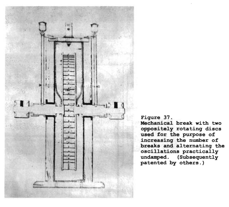
Here [Fig. 37] I show an apparatus that was installed in the Houston Street laboratory prior to the other break because I wanted to get as high a number of impulses as possible. The drawing dates from the spring of 1896. It is a break with which I could reach from 15,000 to 18,000 interruptions per second. I used it very much until later I found it was not necessary. That is the innocent device which Marconi thought a great invention.
Counsel
This is also a rotary gap?
Tesla
Yes, and it consists of two discs of aluminum with teeth of aluminum on the side. They were rotated by two motors in opposite directions and as they rotated they alternately opened and closed the circuit. In some instances I used an uneven number of teeth on one and and even number on the other so that I could produce as many breaks as I desired. I will show you later an apparatus more perfect than this one, and of a different kind, in which I have 24 stationary contacts, and 25 rotating elements that established the contact and broke it, so that by one revolution I obtained 24 times 25, or 600 interruptions [per revolution].
Counsel
Whenever you say "the break", you mean "a spark gap"?
Tesla
Yes; otherwise I use the term "circuit controller"
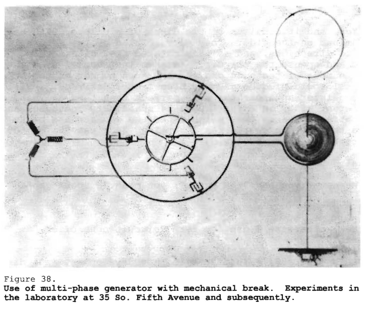
This [Fig. 38] illustrates another development in a different direction. In order to increase the number of breaks, I employed currents of different phase. I had in my labortory, permanently, a two-phase dynamo and I could get phases between; that is, from two phases, 90 apart, I could obtain four phases, 45 apart. Here is an arrangement shown as I had it, working with three phases [60 apart, and could obtain six phases, 30 apart], and later on I had one with four phases [45 apart, and could obtain eight phases 22 1/2 apart]. You see, as I multiplied the number of the phases, I increased the number of the fundamental discharges.
Counsel
What is the date of this apparatus?
Tesla
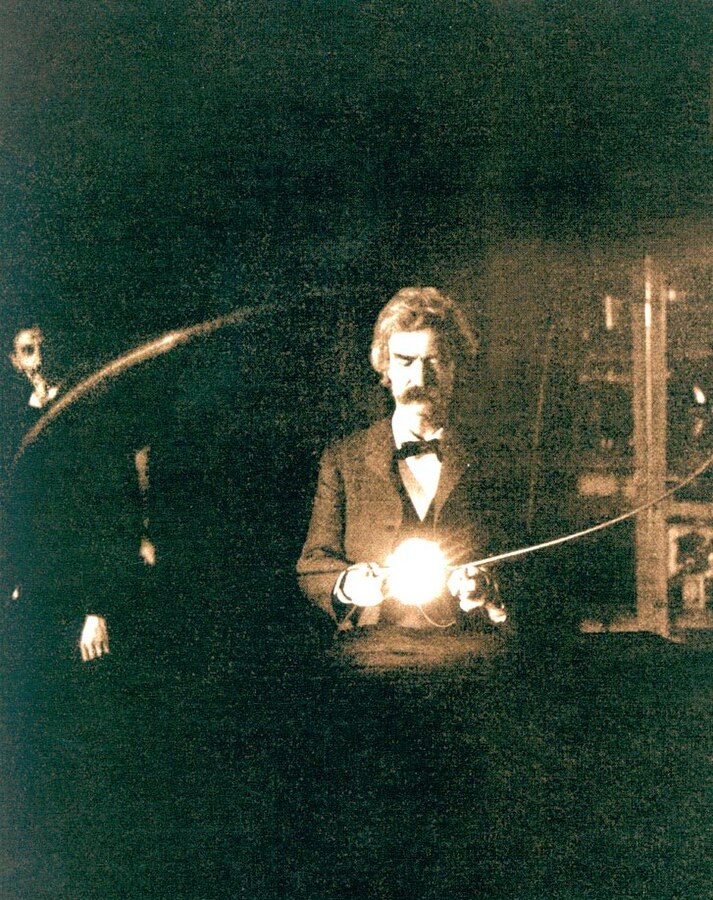
This I employed already in the 35 South Fifth Avenue laboratory, because I remember that I gave entertainments to several scientific societies and it was then present there. I know on one occasion there was the Society of Architects, and another, the Electrotherapeutic Society, and then I had distinguished men like Mark Twain and Joseph Jefferson -- I gave them a demonstration which was published in Martin's article in the Century Magazine of April 1895, and I know that on these occasions I used a two-phase arrangement. Later on I made it four phase. That apparatus existed, therefore, prior to the destruction of my laboratory in 1895.
Counsel
Do you recall any publication in which this diagram was illustrated?
Tesla
I made no publication, and I vividly remember that when I installed my apparatus on Long Island I had an arrangement with four transformers and four phases 45 apart. After I had been using this apparatus there, several years afterwards, I ran across a patent, I believe held by the General Electric Company, describing precisely the same arrangement. [*] It was a similar experience as with that patent of Fessenden on the compressed air condenser. Any time I want to use these improvements all I need to do is to produce my records and that will settle the patents.
Counsel
What was that drawing [Fig. 38]?
Tesla
This is from an old patent drawing which was made by Mr. Netter.
Counsel
But that did not go to patent?
Tesla
No. I have hundreds of inventions that were to be patented but side-stepped. The expense was too great and I coul not do it. This form of apparatus with two and four phases was used prior to the destruction of my laboratory in 1895, and it was installed on a large scale with four phases in my plant on Long Island with which I was to telephone around the world, but that is a long story.
Counsel
In that use you made of it at your laboratory, was that connected up as shown there [Fig. 38], to an antenna?
Tesla
I used the apparatus, yes, in connection with the antenna too, but this is from a patent drawing in which an antenna is shown; I mean, I used it in every connection. [Fig. 38] illustrates an antenna with my transmitting circuit, but the apparatus was used in all my work, in all my investigations.
Counsel
And when this was connected in and used in an antenna, did you use it as in other instances -- go off and listen to the notes which you received?
Tesla
Oh, certainly. But I remember that, besides this, I had different kinds of apparatus. Then I had a sensibly damped wave because at the time I still was laboring under the same difficulties as some do this day -- I had not learned how to produce a circuit which would give me, with very few fundamental impulses, a perfectly continuous wave. That came with the perfection of the devices. When I came to my experiments in Colorado, I could take my apparatus like that and get a continuous or undamped wave, almost without exception, between individual discharges.
Counsel
Speaking of your not having perfectly undamped waves at that time, you were referring to that character of circuit?
Tesla
Yes, but with another kind of circuit I could, of course. The advantage of this apparatus was the delivering of energy at short intervals whereby one could increase activity, and with this scheme I was able to perform all of those wonderful experiments which have been reprinted from time to time in the technical papers. I would take energy out of a circuit at rates of hundreds or thousands of horsepower. In Colorado, I reached 18 million horsepower activities, but that was always by this device: Energy stored in the condenser and discharged in an inconceivably small interval of time. You could not produce that activity with an undamped wave. The damped wave is of advantage because it gives you, with a generator of 1 kilowatt, an activity of 2,000, 3,000, 4,000, or 5,000 kilowatts; whereas, if you have a continuous or undamped wave, 1 kilowatt gives you only wave energy at the rate of 1 kilowatt and nothing more. That is the reason why the system with a quenched gap has become popular.
I have refined this so that I have been able to take energy out of engines by drawing on their momentum. For instance, if the engine is of 200 horsepower, I take the energy out for a minute interval of time, at a rate of 5,000 or 6,000 horsepower, then I store [it] in a condenser and discharge the same at the rate of several millions of horsepower. That is how these wonderful effects are produced. The condenser is the most wonderful instrument, as I have stated in my writings, because it enables us to attain greater activities than are practical with explosives. There is no limit to the energy which you can develop with a condenser. There is a limit to the energy which you can develop with an explosive.
A common experiment, for instance, in my laboratory on Houston Street, was to pass through a coil energy at a rate of several thousand horsepower, put a piece of thick tinfoil on a stick, and approach it to that coil. The tinfoil would melt, and would not only melt, but while it was still in that form, it would be evaporated and the whole process took place in so small an interval of time that it was like a cannon shot. Instantly I put it there, there was an explosion. That was a striking experiment. It simply showed the power of the condenser, and at that time I was so reckless that in order to demonstrate to my visitors that my theories were correct, I would stick my head into that coil and I was not hurt; but, I would not do it now.
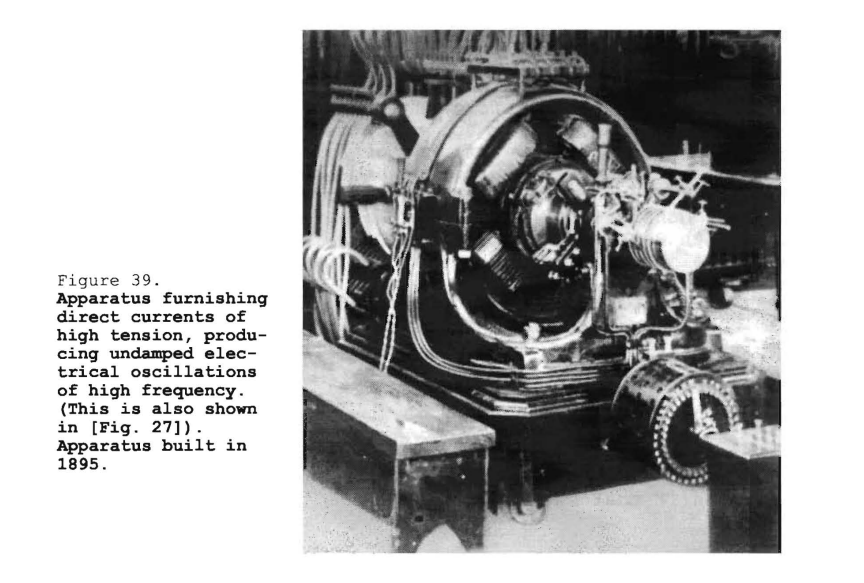
[Fig. 39] shows a four-phase machine which was furnished me by the Westinghouse Electric Company at the close of 1895. My laboratory burned out in May, and I urged my friend, Mr. Albert Schmidt, who was the Superintendent, to give me this alternator as soon as possible. He worked day and night until he got it out, and he certainly did notable work because while the machine was rated at 30 horsepower, I have run it at 150 horsepower.
By the way, and this is a painful reflection, it was Schmidt and I who developed this type of frame and this general arrangement which is universally adopted now -- a base, with the magnets cast below, split at the center line, and a corresponding upper part. That is now used everywhere. I remember years ago, some of my friends, Messrs. Crocker and Wheeler, started with those long magnets and I told them, "The sooner you throw these away and adopt this construction, the better it will be for you." They have got it now; it is all right.
Counsel
How is this machine [Fig. 39] shown in connection with that?
Tesla
This dynamo [Fig. 39], you see, is a two-phase machine; that is, I develop from it currents of two-phase. Now, there are four transformers, you see them down here [lower left of Fig. 39], that furnish the primary energy. From these two phases I develop four phases. [However,] this involves something else which I have referred to before; namely, an arrangement which enables me to produce from these alternating currents direct currents and undamped -- absolutely undamped isochronous oscillations of any period I like.
This is accomplished in the following manner: The secondaries of the four transformers could each develop 44,000 volts. They were specially built for me by the Westinghouse Company. They could, however, be connected in such a way that each would give 11,000 volts, and then I would take these 11,000 volts and these four phases and commutate them by a commutator consisting of aluminum plates, or aluminum segments, which were rotated in synchronism with the alternator. Then I obtained a continuous pressure; that is, direct current of a tension of 44,000 volts, and with these 44,000 volts I charged my condensers. Then by discharging the condensers, either through a stationary gap or through a gap with a mechanical interrupter, I obtained any frequency I desired, and perfectly undamped waves. This arrangement was installed in 1901 in my wireless plant at Long Island, with which I was to telephone around the world.
Counsel
Who built that machine?
Tesla
The Westinghouse Company, [under direction of] Mr. Albert Schmidt, Superintendent. It was especially built for me and furnished to my laboratory on Houston Street.
While I was with the Westinghouse Company, I did two things in addition to bringing my motors to them. I had discovered that Bessemer steel was a much better material for transformers and motors than the soft iron which was previously used. When I came to Pittsburgh, my motors gave results which their motors could not at first produce, and I told them that I had used Bessemer steel. I discovered, in following up the analysis of the steels which were used, that the Bessemer was not steel but really soft iron. The Westinghouse people then adopted my suggestion. At first, Mr. Shallenberger and other electricians there objected very much, but I persuaded them and when the transformers were built we found that we could get 2 1/2 times the output we got before.
The Westinghouse people kept it a secret for a long time and no one understood how they could make such fine transformers, but all they did was to use the Bessemer steel, on my suggestion, instead of the soft iron the General Electric and other people used. Mr. Westinghouse especially requested me to join efforts with Mr. Schmidt and improve the design of his machines, and we did so. We evolved this design, introduced the ready-made coils, which are pressed on the armature, and other improvements. I took a couple of patents out with Mr. Schmidt, and Mr. Westinghouse was very nice about it. I think he compensated me with $10,000, or something like that, for my suggestions.
Counsel
You have spoken of the use of that machine at Houston Street. In what way was it used?
Tesla
I used this machine, as I said, either to produce alternating currents and then interrupt them with a mechanical break at the high peaks of the wave; or, I used alternating currents and interrupted them with an independent rotating break having a great number of teeth. Or, I generated continuous currents by commutating the high tension alternating currents of the transformer. At that that time I had two transformers from which I obtained a constant pressure, charged the condenser, and produced undamped waves of any frequency I wanted. As to the machine here [Fig. 39], that is the way it was arranged. It was for the generating of continuous electromotive force and production of undamped waves -- from 1895 and on.
Counsel
What sort of apparatus was it connected up to for the purpose of absorbing these waves?
Tesla
I was the same as shown here [Fig. 38]. It was connected to the condensers, and these condensers were discharged through a primary which excited the secondary; the antenna was included in the secondary. At other times we discharged the condensers directly so that I could use the antenna without the secondary.
Counsel
In the same way did you note the operation of these waves?
Tesla
We did of course, only in the most cases the instrument of reception was different. When I operated with these continuous, or undamped, waves, generated in this way, I usually went to high frequencies. I did operate [at] a very frew thousand, but that gave me a smaller output. Such a machine you have to operate at high frequencies to get power.
Counsel
What do you mean by high frequencies?
Tesla
I mean frequencies of 30,000, 40,000, 50,000, or something like that.
Counsel
And by means of that machine, you put undamped waves of frequency about 50,000 into that antenna at Houston Street in 1895?
Tesla
No, not in 1895. Late in 1895 the machine was furnished and I began to operate in early 1896. That is when I began to operate.
Counsel
Then you did this, that I speak of, 1896?
Tesla
Yes, from 1896 to 1899, right along.
Counsel
When you used frequencies like that in your antenna, was your antenna tuned or untuned?
Tesla
I could not use it untuned. That would be absurd.
Counsel
What form of device did you use, and where did you use it, for noting the generation of these oscillations or waves in the antenna?
Tesla
I suppose I had hundreds of devices, but the first device that I used, and it was very successful, was an improvement on the bolometer. I met Professor Langley in 1892 at the Royal Institution. He said to me, after I had delivered a lecture, that they were all proud of me. I spoke to him of the bolometer, and remarked that it was a beautiful instrument. I then said,
"Professor Langley, I have a suggestion for making an improvement in the bolometer, if you will embody it in the principle."
I explained to him how the bolometer could be improved. Professor Langley was very much interested and wrote in his notebook what I suggested. I used what I have termed a small-mass resistance, but of much smaller mass than in the bolometer of Langley, and of much smaller mass than that of any of the devices which have been recorded in patents issued since. Those are clumsy things. I used masses that were not a millionth of the smallest mass described in any of the patents, or in the publications. With such an instrument, I operated, for instance, in West Point -- I received signals from my laboratory on Houston Street in West Point.
Counsel
This was then the machine that you used when working with West Point?
Tesla
I operated once or twice with it at that distance, but usually as I was investigating in the city. My work at that time was to prepare for the development of a commercial plant, and with me the question was not to transmit signals, but to see what intensity I could get to put me in position to calculate out my apparatus, the dimensions and the forms, before I began the undertaking. It was nothing but preparatory work for the construction of a commercial plant, and I demonstrated its practicability through my experiments, a plant which was to accomplish much more than all others.
Counsel
What was the horsepower activity in the oscillating circuits when you used this machine?
Tesla
Usually something like 50 horsepower, and I would get, I should say, approximately 30 horsepower in the antenna; that is I would get 30 horsepower in the oscillating circuit.
Counsel
I understood a little while ago when you made the statement of using several thousand horsepower put into a condenser, you could take out of the condenser a million horsepower. I wondered if you got the same condition with this machine.
Tesla
Yes, I charged the condenser with 40,000 volts. When it was charged full, I discharged it suddenly, through a short circuit which gave me a very rapid rate of oscillation. Let us suppose that I had stored in the condenser 10 watts. Then for such a wave there is a flux of energy of (4 x 10⁴)2, and this is multiplied by the frequency of 100,000. You see, it may go into the thousands or millions of horsepower.
Counsel
What I wanted to get at was, did that depend upon the suddenness of the discharge?
Tesla
Yes. It is merely the electrical analogue of a pile driver or a hammer. You accumulate energy through a long distance and then you deliver it with a tremendous suddenness. The distance through which the mass moves is small -- the pressure immense.
Counsel
Did you find that that was the best condition for transmitting energy without the use of wire?
Tesla
No, I did not use that method when I was transmitting energy. I used it only in the production of those freaks for which I have been called a magician. If I had used merely undamped waves, I would have been an ordinary electrician like everybody else.
Counsel
You have referred to some delicate receiving instruments. Did you have any trouble with those burning out on account of static?
Tesla
My dear sir, I burned out so many instruments before I discovered what was the matter with them! They burned out instantly until I learned how to make them so that they could not burn out. Yes, that was a great trouble in the beginning.
Counsel
Did you succeed in getting them so they would not burn out?
Tesla
Yes. If lightning struck close by, it would not burn out my instrument that has a millionth of the smallest mass used in the instruments of others.
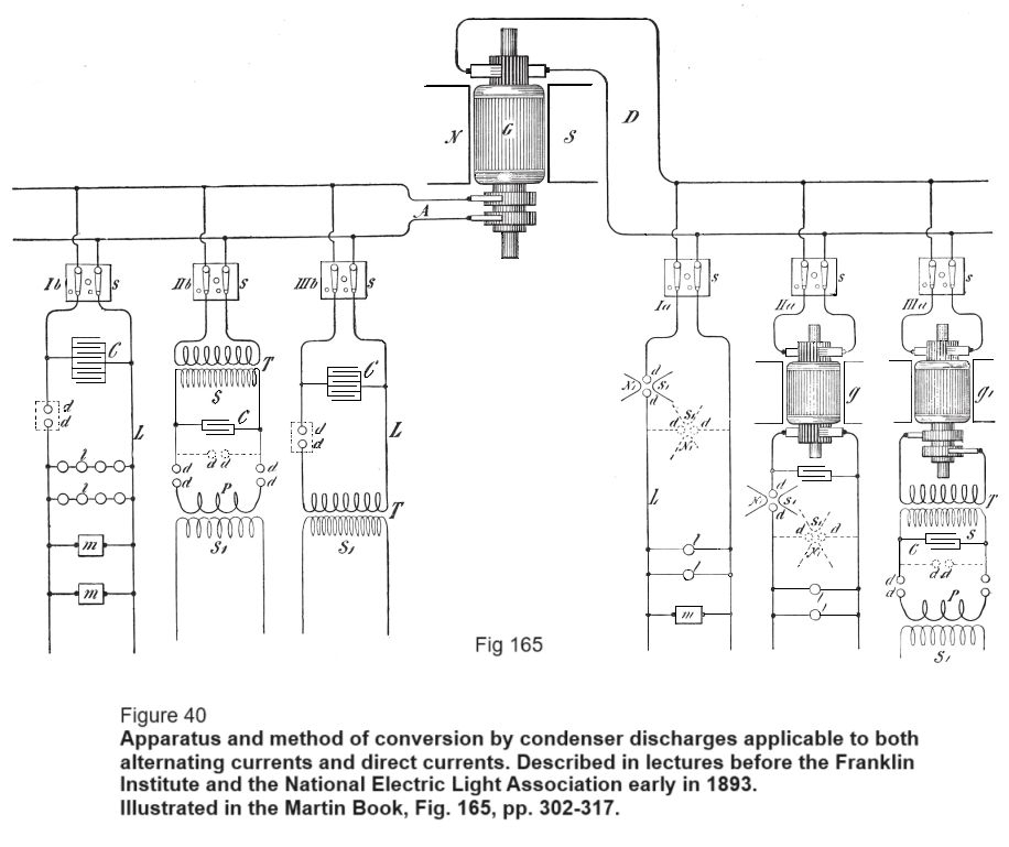
This [Fig. 40] is a systematic representation of the various ways which I gave in my lecture before the Franklin Institute and the National Electric Light Association, embodying the general arrangements for the obtainment of continuous waves, undamped or damped waves, from direct and alternating current supply. On the one side [right] you have direct, on the other side alternating current supply. Some electricians have had difficulties in operating some of this apparatus. I had none. I can take an ordinary circuit of 50 volts and produce from it absolutely undamped oscillations and never have the slightest difficulty about it.
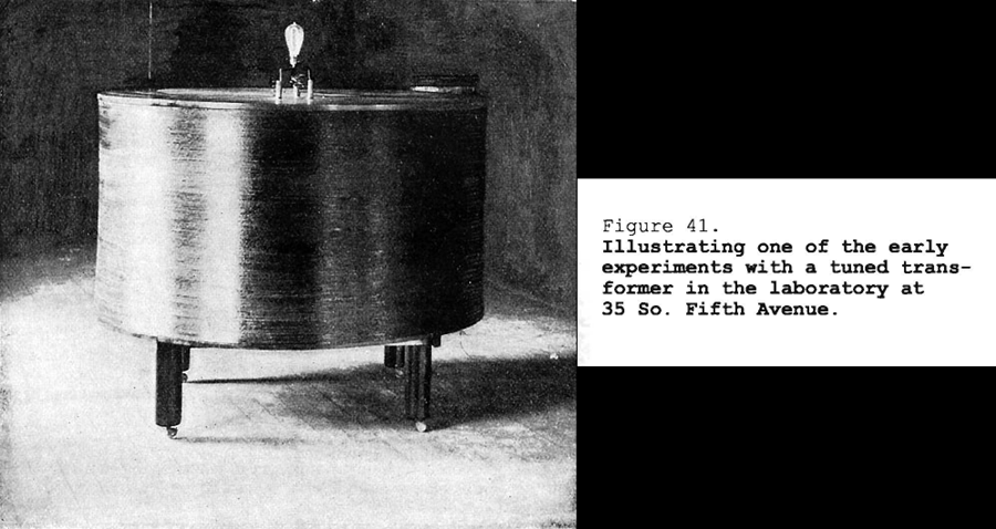
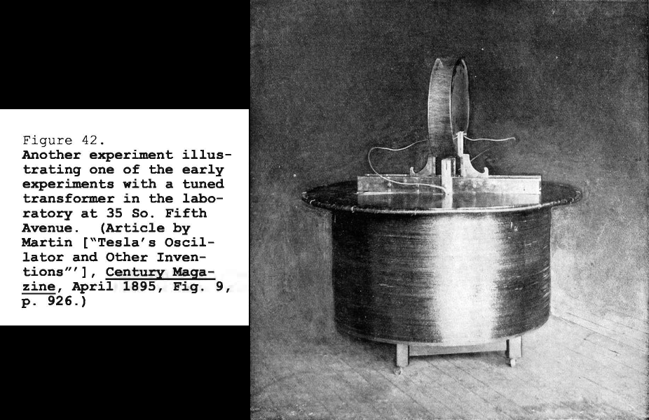
Now I come to a few pieces of apparatus which I used in the Houston Street laboratory and the South Fifth Avenue laboratory. I have here [Fig. 41] what you might call a tuning coil. I employed usually another secondary and had my condensers on the table. You see one of the coils in action. This is a tuned circuit which responds to electromagnetic waves which are sent through the room.
Counsel
This is being used as a receiver of waves?
Tesla
Yes.
This [instrument shown in Fig. 42] was used in the laboratory on South Fifth Avenue. Here [large circular disc positioned on top of coil] is the tuning table with the condensers, a thick primary, and another secondary wire. Sometimes I would operate with two vibrations and I would tune the first circuit to one and the second to the other. Here [referring to cabnets in back of room] you see some of my historical apparatus. Professor Fairfield Osborn[*] came once to my laboratory and said to me, "Why on earth do you keep it in this laboratory?" I had all of this apparatus, 400 pieces, absolutely priceless and he offered to take it over to the Museum. But I did not heed his advice, and it is gone.
Counsel
Where were the waves sent from?
Tesla
The whole room was energized by electromagnetic waves and the receiver responded at any place in the hall. The hall was bigger than this room [shown in Fig. 42], twice as long, and anywhere the intensity of action was the same. These discs [vertical, on top of tuning table] were, I think, about 14 or 15 inches in diameter, and you could see the streamers [shown as white between the discs] anywhere in the room. In a hall twice as long as this, wherever I placed the instrument, it would respond to the electromagnetic waves.
Counsel
In this particular instance you are speaking of, the waves were generated right there at 35 South Fifth Avenue?
Tesla
Yes.
Counsel
Was that the apparatus in which you had the primaries running entirely around the room?
Tesla
Yes. This was shown to many people and societies.
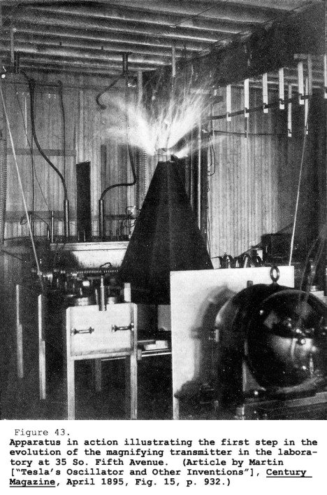
This [Fig. 43] shows the first single step I made toward the evolution of an apparatus which, given primary oscillations, will transform them into oscillations capable of penetrating the medium. That experiment, which was marvelous at the time it was performed, was shown for the first time in 1894. I remember the incident perfectly. I called Mr. Edward Adams, the banker, to come and see it, and he was the first man to observe it and to hear my explanation of what it meant.
Another print showing the generator drive belt and pulley, you can just make out the wire drops to provide DC power to the field electromagnets.
This coil, which I have subsequently shown in my patents Nos. 645,576 and 649,621, in the form of a spiral, was, as you see, [earlier] in the form of a cone. The idea was to put the coil, with reference to the primary, in an inductive connection which was not close -- we call it now a loose coupling -- but free to permit a great resonant rise. That was the first single step, as I say, toward the evolution of an invention which I have called my "magnifying transmitter." That means, a circuit connected to ground and to the antenna, of a tremendous electromagnetic momentum and small damping factor, with all the conditions so determined that an immense accumulation of electrical energy can take place.
It was along this line that I finally arrived at the results described in my article in the Century Magazine of June 1900. [Fig. 43] shows an alternator; not the alternator that was furnished for my laboratory on Houston Street -- that was another one, [but] at 35 South Fifth Avenue [and] operated on the same principle. Here [lower left] are the condensers, primary, and all the rest. The discharge there was 5 or 6 feet, comparatively small to what I subsequently obtained. I have produced discharges of 100 feet, and could produce some of 1,000 feet if necessary, with the greatest facility.
Counsel
Mr. Tesla, at that point, what did you mean by electromagnetic momentum?
Tesla
I mean that you have to have in the circuit, inertia. You have to have a large self-inductance in order that you may accomplish two things: First, a comparatively low frequency, which will reduce the radiation of the electromagnetic waves to a comparatively small value, and second, a great resonant effect. That is not possible in an antenna, for instance, of large capacity and small self-inductance. A large capacity and small self-inductance is the poorest kind of circuit which can be constructed; it gives a very small resonant effect. That was the reason why in my experiments in Colorado the energies were 1,000 times greater than in the present antenna.
Counsel
You say the energy was 1,000 times greater. Do you mean that the voltage was increased, or the current, or both?
Tesla
Yes [both]. To be more explicit, I take a very large self-inductance and a comparatively small capacity, which I have constructed in a certain way so that the electricity cannot leak out. I thus obtain a low frequency; but, as you know, the electromagnetic radiation is proportionate to the square root of the capacity divided by the self-induction. I do not permit the energy to go out; I accumulate in that circuit a tremendous energy. When the high potential is attained, if I want to give off electromagnetic waves, I do so, but I prefer to reduce those waves in quantity and pass a current into the earth, because electromagnetic wave energy is not recoverable while that [earth] current is entirely recoverable, being the energy stored in an elastic system.
Counsel
What elastic system do you refer to?
Tesla
I mean this: If you pass a current into a circuit with large self-induction, and no radiation takes place, and you have a low resistance, there is no possibility of this energy getting out into space; therefore, the impressed impulses accumulate.
Counsel
Let's see if I understand this correctly. If you have radiation or electromagnetic waves going from your system, the energy is wasted?
Tesla
Absolutely wasted. From my circuit you can get either electromagnetic waves, 90 percent of electromagnetic waves if you like, and 10 percent in the current energy that passes through the earth. Or, you can reverse the process and get 10 percent of the energy in electromagnetic waves and 90 percent in energy of the current that passes through the earth.
It is just like this: I have invented a knife. The knife can cut with the sharp edge. I tell the man who applies my invention, you must cut with the sharp edge. I know perfectly well you can cut butter with the blunt edge, but my knife is not intended for this. You must not make the antenna give off 90 percent in electromagnetic and 10 percent in current waves, because the electromagnetic waves are lost by the time you are a few arcs around the planet, while the current travels to the uttermost distance of the globe and can be recovered.
This view, by the way, is now confirmed. Note, for instance, the mathematical treatise of Sommerfeld, [*] who shows that my theory is correct, that I was right in my explanations of the phenomena, and that the profession was completely misled. This is the reason why these followers of mine in high frequency currents have made a mistake. They wanted to make high frequency alternators of 200,000 cycles with the idea that they would produce electromagnetic waves, 90 percent in electromagnetic waves and the rest in current energy. I only used low alternations, and I produced 90 percent in current energy and only 10 percent in electromagnetic waves, which are wasted, and that is why I got my results.
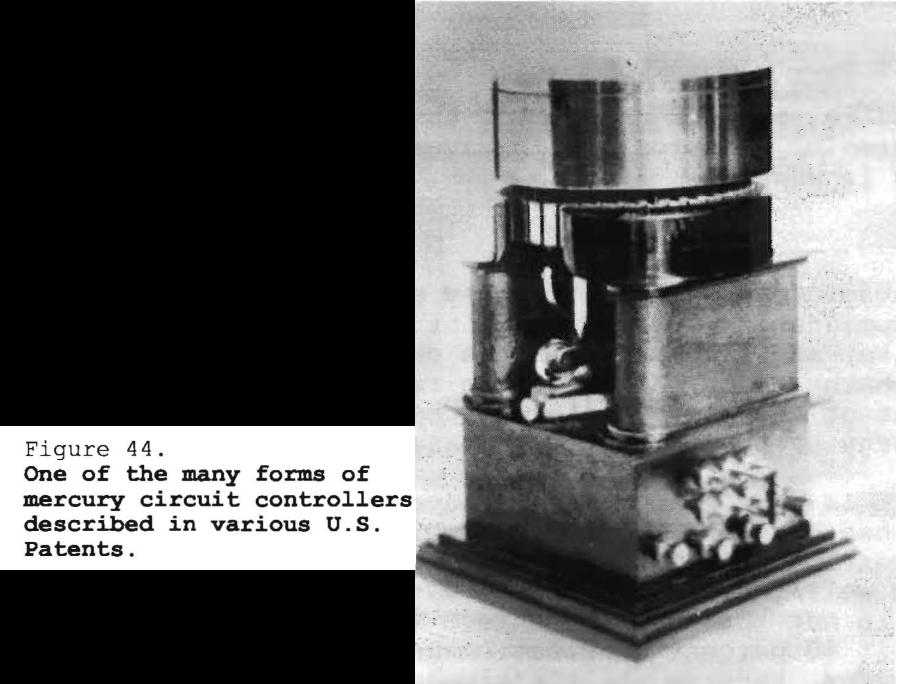
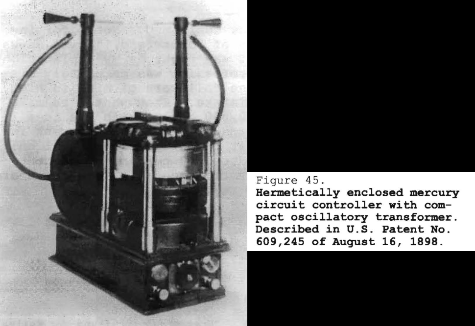
609,245 - 609,246 - 609,247 - 609,248 - 609,249 - 609,251 - 611,719 - 613,735
This [Fig. 44] shows a further development in the direction of perfecting a way of making and breaking the current, and illustrates one the simplest forms of my apparatus, which was special built with a mercury interrupter inside, capable of considerable frequency. That was operated from an ordinary circuit of supply and could stand a current of 20 or 25 amperes. It was a very compact instrument. I had dozens of these instruments, and obtained eight patents on the same; they were all issued in 1898.
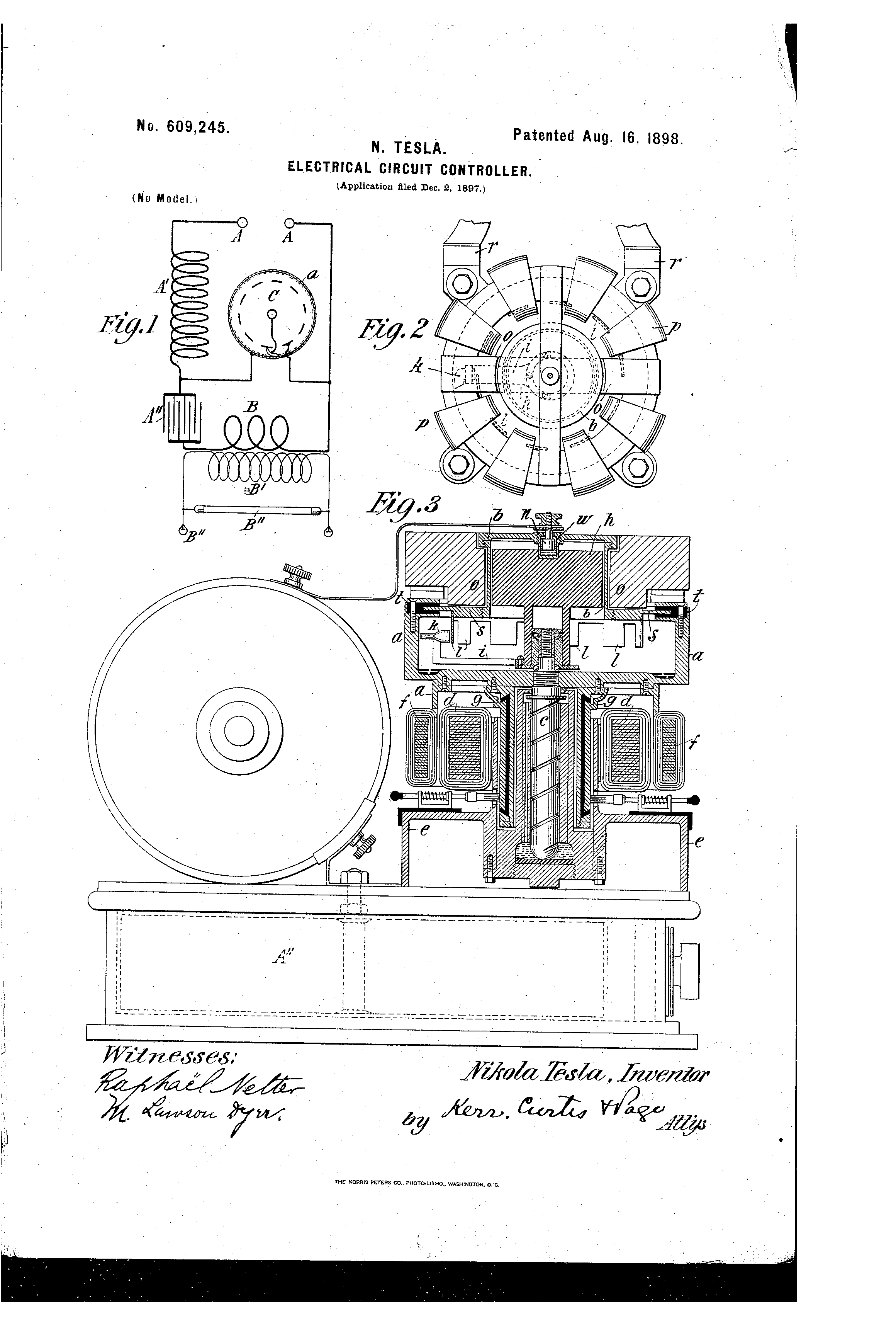
The next I did was to enclose the mercury break hermetically [Fig. 45]. You see, here [Fig. 46, overleaf] is a motor, especially designed, rotating this pulley.
In this pulley [referring to the cross-sectional diagram] is produced a jet of mercury, and there are teeth running around which make and break the current. The whole is encased hermetically. Here I have a German-silver cup that is nickel plated on the inside, and there is a field magnet outside which holds the mercury jet stationary while the pulley rotates. I could get with this instrument about 2,000 cycles very nicely, and it was a machine that would give an output of about 1 kilowatt. It was a fairly efficient instrument, perhaps 80 percent of the energy of the circuit was obtained in the secondary.
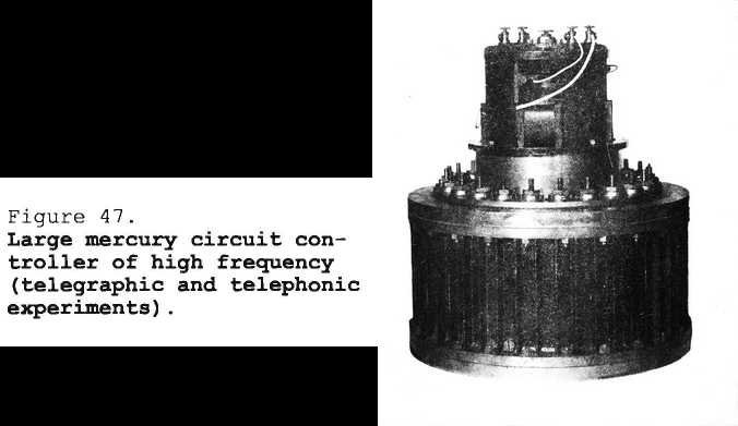
The arrangement was simply this. I had a number of studs with cups which were insulated, 24 if I recollect rightly. In the interior was a mechanism that lifted the mercury, threw it into these cups, and from these studs there were thus 24 little streamlets of mercury going out. [*] In the meantime, the same motor drove a system with 25 contact points, so that for each revolution I got a product of 24 times 25 impulses, and when I passed these impulses through a primary, and excited with it a secondary, I got in the latter complete waves of that frequency.
Counsel
What frequency, then, did you get in your secondary?
Tesla
Oh, I could get in this, 600 per revolution.
Counsel
You mean 600 trains?
Tesla
No, 600 waves. Assume then, 600 impulses per revolution and suppose that I rotated it 100 times per second [6,000 RPM]; then I would get 600 times 100, or 60,000 primary impulses [per second], and in the secondary a frequency of 60,000 complete cycles. The primary impulses were unidirectional. They came from the direct current source, but in the secondary they were alternating -- full waves.
Counsel
How persistent were those waves?
Tesla
They were entirely persistent. I had 60,000 per second absolutely undamped waves; they could not be damped.
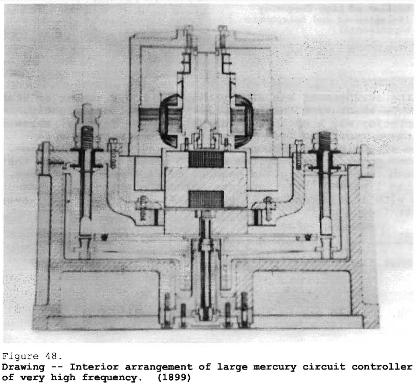
That [Fig. 48] was another type. I had probably 50 or 60 different instruments; in fact, I spent a little fortune on these devices, but some of them have been very valuable, and I do not know but that they will take an important place in the art. They are used very extensively.
The other day, some time ago, a German concern, in recognition of my inventions, made me a present of a very nicely developed interrupter which they had been manufacturing along the lines of my patents. My patents expired; they used the inventions and built up a business, and felt that at least they ought to give me one instrument, and they did. It was very nice.
Counsel
This then, as operated by you, produced undamped waves. Will you tell us just what use you made of it?
Tesla
Oh, I used it just exactly as I used the high frequency alternators. I would energize the primary circuit, and then in the secondary connect the antenna. You see, with an apparatus about 18 inches in diameter, I could get 2 kilowatts in undamped waves.
Counsel
When was this?
Tesla
These instruments all were made, practically all -- I had perhaps 40 or 50 of them -- prior to 1899. When I came to my plant on Long Island, I did some further work on them, but I used the old casings and simply changed the interior construction.
There was one construction I had, a very fine thing in which I did not produce any streams. It was so devised that the mercury filled these pockets, and I had 24 little droplets coming out of these places. Then, on the other hand, I had curved arms running around and forcing mercury out under small pressure due to a difference in the length of two columns in the curved arm. I had just the drops meeting, and there was no mercury flowing out in reality. There was simply mercury touching mercury, the contacts being at a distance of about 1/64 inch. These devices worked very well indeed. I have this little instrument from Germany -- of course the Germans do everything so thoroughly -- it is very reliable. I can pass through it regularly 20 amperes, and it works well -- no trouble at all. This [Fig. 48] is a little bit different in construction but, as I say, my patents described many forms. I have spent a lot of gray matter in developing these instruments.
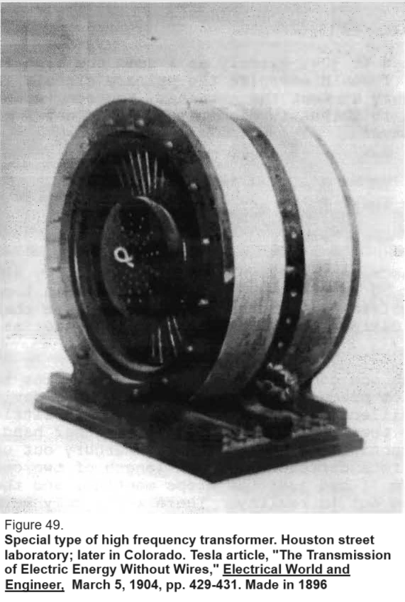
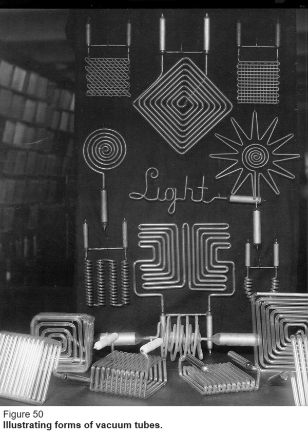
This [Fig. 50] does not refer to wireless telegraphy, but it does refer to wireless transmission of energy. These [upper] are forms of tubes I used, and these [on table] are the forms that I proposed to use in a larger plant when transmitting energy. This is, in fact, the ideal application of the transmission of wireless energy because the lighting can be effected in isolated places at a much smaller cost than is possible by any other method known. I also believe that nowhere as yet has a source of illumination been produced, neither the tungsten or the mercury arc nor anything else, which has the efficiency in light production that my tubes have; but they can only be used to produce light on a large scale, and that project, unfortunately, has not yet been carried out; but I think it will.
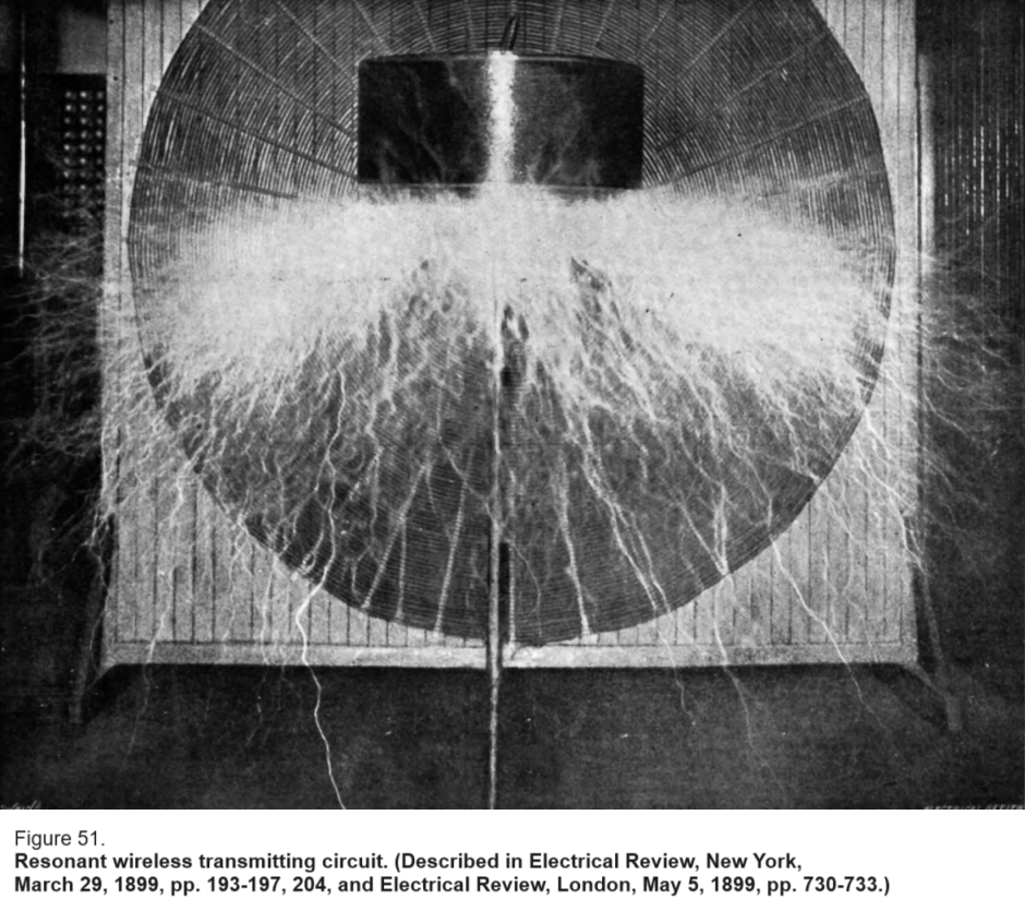
This [Fig. 51] is the transmitter which was already so far developed that I obtained discharges of 16 feet and a tension of 4 million volts. The secondary [flat spiral] usually connects to the antenna, and this [coil on vertical stand] is another tuning coil to adjust the oscillations to a low frequency. Now, it is a mere matter of proportioning this circuit to the antenna in order to transmit, with the same apparatus I built in 1895, 1896, and 1897, messages across the Atlantic with the greatest facility. I will agree at any time to construct an apparatus exactly as I have described at that time and, without the slightest change, I will effect transmission across the Atlantic as easily as rolling off a log.
Counsel
Is that a spark apparatus?
Tesla
Yes, in this instance it was a spark apparatus; but I operated it also without a spark, with alternating current. I operated it with damped waves or with undamped waves. But remember that I had a system with small capacity, large self-induction -- no outflow of energy. Energy could not radiate; that is the reason why I got this tremendous pressure which you cannot get in an antenna which radiates too much energy in electromagnetic waves.
Counsel
Mr. Tesla, speaking about that apparatus you said that the energy could not get out. How was the transmission then made, as for instance, across the Atlantic, or elsewhere? Is it through these earth currents that you spoke of?
Tesla
Yes, of course, through the earth currents. If I simply generated electromagnetic waves, I would be in the same box that Marconi is in, or anybody else; I would have to use an awful lot of power and I would not be able to get across. I would have to use a bigger apparatus. But, if I adapt this apparatus to the antenna in the way I want to adapt it, there is no difficulty of transmitting across the Atlantic with this very same apparatus.
I understand that Atlantic Communication Company made recently, in a suit, an experiment -- I believe Pickard [*] told me about it -- [where] they constructed a coil according to my inventions, and then they telegraphed -- I don't know, 200, 300, or 400 miles. When Pickard told me about that, I saw that they did not make the test properly. You see, they should have obtained the low frequency by using more primary energy, by adding more condensers, but they did not do that; they only used the capacity which I specified in my patent, which was only, I understand, 0.04 microfarad. They should have added to the condenser [additional] capacity and got down to a lower frequency with a bigger inductance; then they could have telegraphed across the Atlantic. Why not? The same apparatus is used in all of these plants. These stations, every one of them, have adopted the spiral form.
Counsel
Pickard did not understand your disclosures, then, did he?
Tesla
Excuse me, he understood them perfectly.
Counsel
But he did not embody them in the apparatus?
Tesla
He did not do the thing as I would have done it, I will admit that; but, then, there are artists, and then there are others.
Counsel
I do not yet get quite clear just what the effect is of keeping the energy from leaking out from the antenna.
Tesla
Well, sir, I have given you the simplest mathematical formula which, of course, experts are perfectly familiar with. You are not. Now, let me explain.
If we put it in an equation, we will have on one side the decrement of the antenna, and on the other the resistance of the antenna multiplied by the square root of the capacity divided by the self-induction. [*]
Counsel
Yes, I understand. I have heard of that formula; but I do not understand how transmission is effected unless there is radiation.
Tesla
This is a very important thing. We will come to that; I will explain it later.
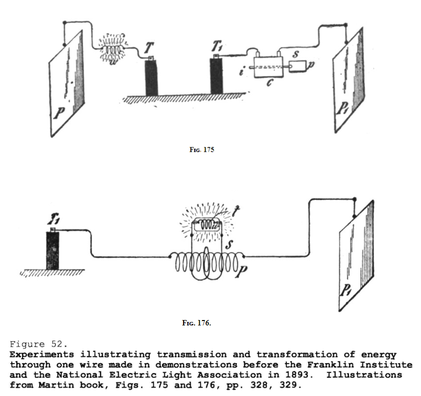
Here [Fig. 52] are illustrated the first experiments I demonstrated in public, in my lectures in the United States, forming the original striking departures -- the first primary steps I made in operating devices, when I showed this new principle of conversion. I passed a current of high tension through one wire, then I reduced the pressure in a secondary; that is now a very common practice.
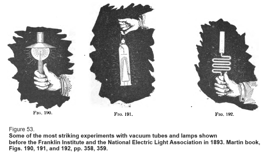
These were the most striking results I showed in the transmission of energy in my lectures before mentioned. You see how far I have gone into the mastery of electrical vibrations in 1893. I stand here [Martin's Fig. 190] in the hall, holding a lamp in my hand, and the energy transmitted lights it. Here again (Fig. 191] I hold a phosphorescent bulb in my hand, and here [Fig. 192] a vacuum tube.
These experiments, I remember, were made in St. Louis. There was a hall with 6,000 or 7,000 people. When I explained how I had shown a phosphorescent bulb to Lord Kelvin in England, and told them that the bulb was going to spring into light, and the current was turned on and it did burst into light, there was a stampede in the two upper galleries and they all rushed out. They thought it was some part of the devil's work, and ran out. That was the way my experiments were received.
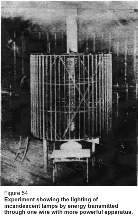
Here [Fig. 54] I show that I have advanced further, much further. This is an experiment in Colorado [*], and as you see, five or six lamps are lighted -- no capacity, just simply a coil into which the current passes. I have not the time to do justice to these photographs now.
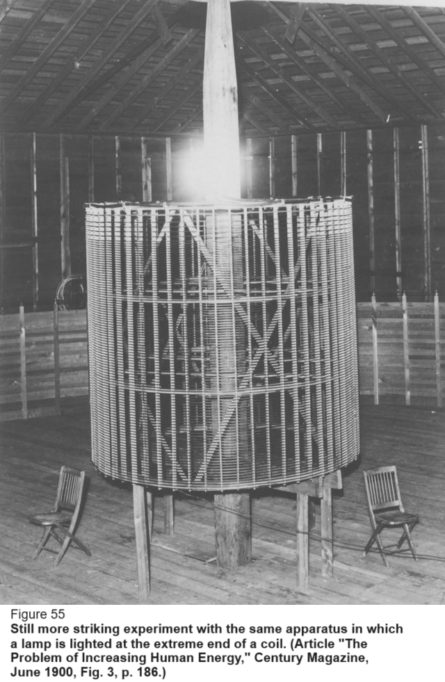
This [Fig. 55] is a wonderful result, showing a further perfection. To give an idea of the power of all these oscillations, I put a lamp on the end of a coil, nothing else, and it is lighted to full brilliance just by reason of the fact that it has a minute capacity, only 4 or 5 centimeters [4.4 or 5.5 picofarads]; that is enough to light it.
Counsel
Where is the other coil?
Tesla
You see it [in the background of] this picture. The coil here is 51 feet in diameter.
Counsel
A wire around the room?
Tesla
No, it is a coil. That [in the picture background] is my secondary. That is the coil which connects to the antenna, you see. But this smaller coil stands free, entirely free, in the center of the big one.
Counsel
Is this apparatus shown here the receiver; that is, is the glow that we see there the indication of received energy?
Tesla
Yes, but that is the energy supplied through one wire. That is, I am now describing various effects. I meant to lead up from the transmission over one [wire] to the transmission through the earth. This is transmission through one wire, but shows what a marvelous oscillation takes place in the circuit when one can light a lamp at the end without any capacity, just a bulb.
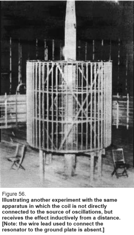
I measured the capacity of the bulb. The capacity was 2 or 3 centimeters [2.2 - 3.3 picofarads], at most, and in order to light a lamp with a capacity of 2 or 3 centimeters, you can appreciate what a tremendous vibration that must have been.
This [Fig. 56] is another experiment, another effect. Here is a coil absolutely disconnected from everything else. I transmit electromagnetic energy to it. There is a lamp at the end and that lamp lights. There is no connection to the coil whatever.
Counsel
And from what source does that coil get its energy?
Tesla
From a [primary] circuit that is 51 feet in diameter, and goes all around. Some of these experiments have been described in my article in the Century Magazine, June 1900.
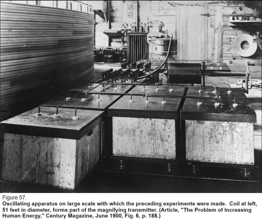
This [Fig. 57] shows the general arrangement of the apparatus. That [middle upper-left], you see here, is a coil 51 feet in diameter; it is my secondary. That is not a thin wire; it is a very thick cable. It is a coil about 9 feet high. This wire goes up to the antenna. Here [lower half] are my condensers, and the transformers behind. There is my self-inductance [with wooden-handle crank], and all the rest.
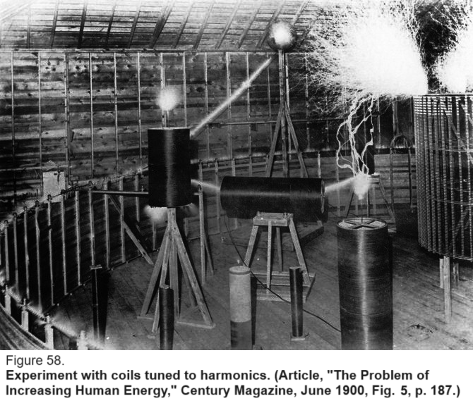
Now you see [in Fig. 58] another thing. I have a number of coils here. Notice the coil in the center. These are coils which I have tuned to various frequencies; that is, to harmonics. They receive electromagnetic energy by induction, and you see the enormous discharge from the center coil, although it is unconnected and at a distance of many feet from the primary.
Counsel
Were those spark generators?
Tesla
I used the spark method and continuous, or undamped, oscillations. I had for their generation ordinary current of 133 cycles and also a street railway current of 550 or 600 volts, from which I produced undamped waves.
Counsel
And this relates to the experiments that are described in the June 1900 Century Magazine?
Tesla
Yes, those experiments of powerful discharges which I showed you were mostly performed in this way, with a few primary impulses and superimposed quicker vibrations.
Counsel
But they were spark discharges?
Tesla
They were spark discharges because, as I said before, working with damped waves we can produce wonderful effects. Operating with undamped waves, we have to stick to the actual capacity of the machine.
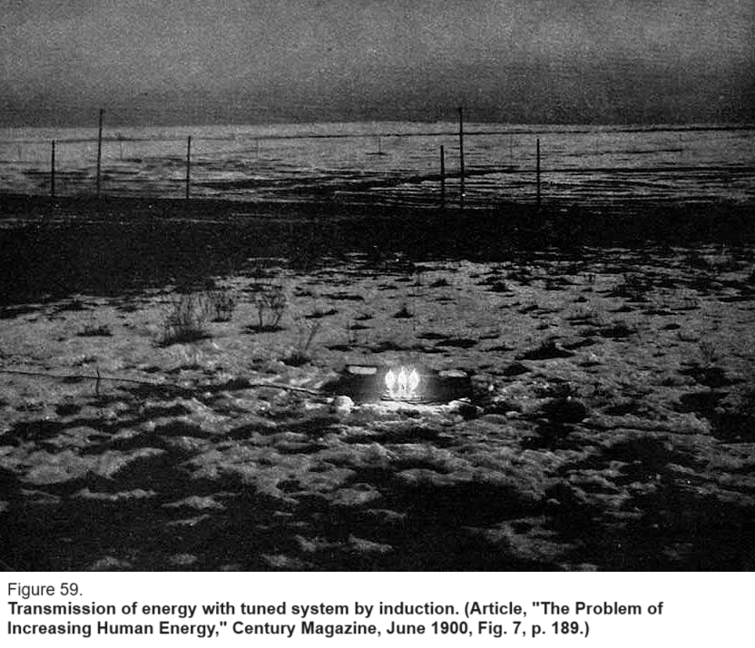
This [shown in Fig. 59] is transmission of energy by induction. Here is a tuned circuit, you see, out in the field with three incandescent lamps and a condenser. The energy is transmitted inductively, from the oscillator. In this case, I have the primary supply circuit, the energizing condenser circuit, the primary inducing circuit, and the secondary in the field as in the fourth circuit, all tuned -- four circuits in resonance.
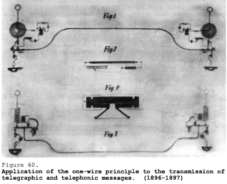
Here [Fig. 60], from a drawing for a patent application not pursued, are shown arrangements in single-wire transmission. All of these arrangements date back to 1896, 1897, and 1898.
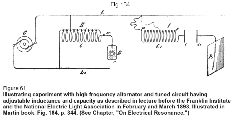
Here [Fig. 61] is a diagram which was published on my lectures before the Franklin Institute and the National Electric Light Association. There I first alliterated and described a complete system of wireless transmission. I show here a generator at one side, a line extending from it, a capacity which is adjustable, as well as an inductance.
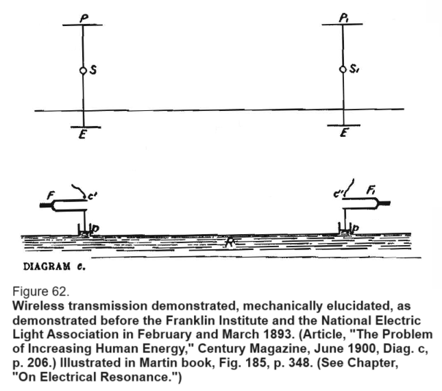
The Problem of Increasing Human Energy: - Diag. c
Franklin Institute 1893 --- Cymatics --- Transmitters
I had, preliminarily to the article in the Century Magazine, to explain, in a popular way, the language of the wireless men; and my friends, R.U. Johnson, and R. Watson Gilder, wanted it explained in the simplest possible manner. This diagram [Fig. 62, topJ illustrates the wireless system as I have described it in my lecture and this one, below, its mechanical analogue which I put in for the benefit of the Century Magazine readers.
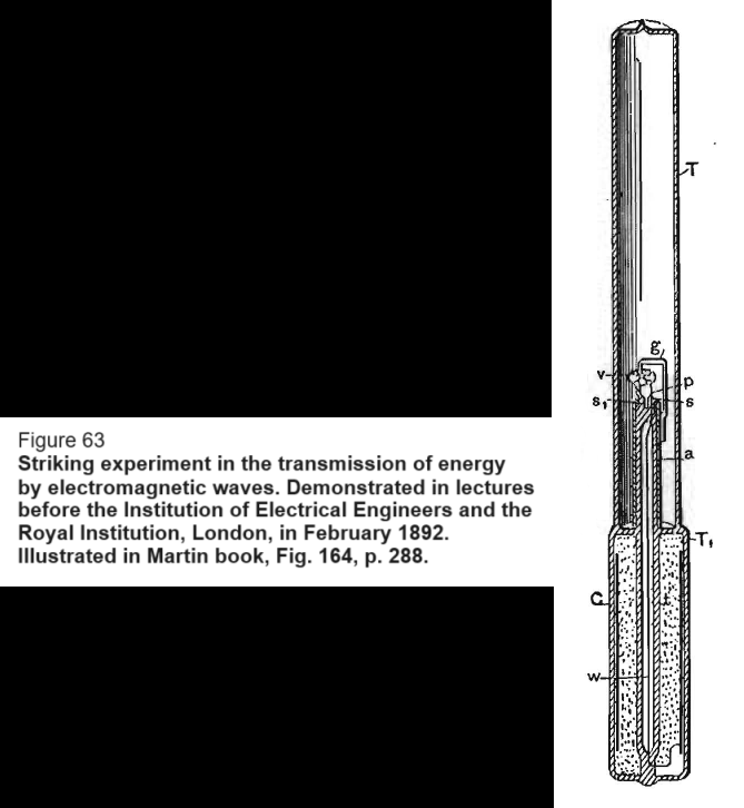
I show two illustrations now. This [Fig. 63], the first one, is to illustrate what I have already partially explained. The experiment was shown before the Institution of Electrical Engineers and the Royal Institution in London in 1892; I will illustrate [nextJ another experiment which I performed in Colorado in 1899 or 1900. That [Fig. 63] is the time where I take a glass tube, hold it in my hand, with nothing nearby. I create electromagnetic energy in the room, and I operate a little fan in that tube by the electromagnetic waves -- a wonderful thing. The scientists simply did not know where they were when they saw it.
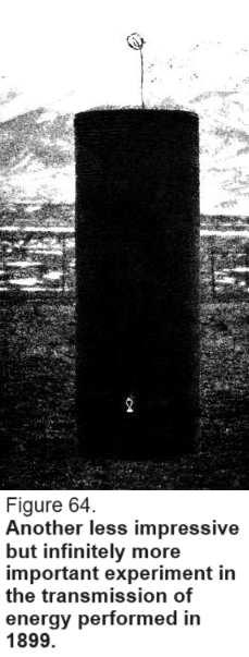
Now I will show you [Fig. 64] the other experiment. How is that experiment performed? Here is a coil, without any antenna, no capacity whatever; just a simple, plain coil. It is placed at a distance from the transmitter and is connected to the ground. I have tuned it so that it forms the fourth circuit of a system of concatenated tuned circuits, and I have another secondary coil here which is likewise tuned, and I light a little lamp. That little lamp is nothing spectacular, nothing that would impress the scientific imagination, but that experiment which I showed you before, while wonderful, was worthless. It never in the world could lead to any development. It was so because of the fact that I employed agencies which were condemned from the very beginning as worthless. But this, here, is a great experiment, marking an epoch in the evolution of the art.
Note that I connect a coil to the ground, impress powerful oscillations on the earth, and draw energy from it. This coil I can put at the antipodes and, if I have my system properly developed it makes absolutely no difference whether it is there or 10 feet from my transmitter. That is the difference between the two experiments.
Counsel
When was that last one?
Tesla
That was in Colorado in 1899 -- at the close of 1899, that last experiment. And the other one was in 1892 before the Institution of Electrical Engineers in London.
Counsel
The difference between those two experiments last described was that the first one in 1892 had no grounding?
Tesla
No grounding.
Counsel
In the second, the coil was grounded?
Tesla
In the second the coil was grounded, and the energy was not that of electromagnetic waves, which is wasted; it was the energy of a current through the ground that produced the effect. This transmission was efficient; the other was worthless.
Counsel
How far was that coil [Fig. 64], in Colorado, from the circuit?
Tesla
That was out in the field. I cannot tell you. The very same experiment was illustrated in the Century Magazine of June 1900 and I know when I wrote it that I gave full particulars. [*]
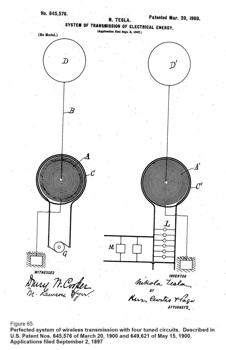
Here [Fig. 65] is my completed wireless system. That was published first in my Belgium patent in 1898. I clearly remember that the day when I received it I entertained the present King [Albert] in my laboratory [August 1898] and explained to him the system.
There [at left] is my primary source of energy, which produces arbitrary oscillations of any kind. This antenna, you see, is grounded; no break in the connection. These two circuits are tuned to a definate frequency, which was arbitrarily adopted. The dynamo supplies oscillations which have been settled on beforehand, of low frequency, of course, and the circuit is excited in the manner I have described.
Here [at right] I have the receiving circuit, similarly connected to ground and to an antenna. Then I have a second tuned circuit in which are included the operating devices.
There is an important thing which is not known to engineers, which I want to point out. I have, in the evolution of the whole system, always laid stress that whenever my high frequency currents are employed, no matter how many circuits there are, those circuits are all to be tuned, preferably to the same note.
In one of these patents [i.e., No. 645,576] I described a transmitter giving minutely the dimensions of the coil, of the condenser, and everything in connection with it.
There is one [other] important point. I have insisted on the tuning of all circuits but, you see, often people have maintained that if a certain thing is not done it will not work, and all that. There is no truth in such statements. That circuit, and that, and that one must be attuned; this is an indispensible condition for economic transmission; but it is not essential to tune this fourth circuit. As a matter of fact, in certain instances I have obtained a better result without tuning the fourth circuit than when I tuned it, and I will tell you the reason why. That is not known to engineers.
If you take this first circuit [C'] entirely away, and leave only that circuit here, the antenna and the ground connection, then that is the ideal condition for the flow of the current in this receiving circuit. Any other circuit you bring near to that excited circuit with the antenna will draw energy from it and tend to pull down the oscillation in the latter circuit and diminish the resonant rise. No matter what you link to the antenna circuit, and how you link it, the energy you take away from that circuit will always tend, being frictional, to diminish the resonant rise. Now the art consists in reducing as much as possible the energy necessary for the signal, and in that regard the evolution of dectectors as the audion of Dr. DeForest, and of other such devices, is in the proper direction, rational and good. But the ideal condition requires that you should have here a device which only requires pressure and no current; and once you have a device which does not need any current but merely acts by pressure and has no internal capacity, so that there will be no capacity current in the circuit, then that is the ideal receiver.
There are two ways in which you can operate if you have a receiver of that kind. One is by linking, closely, your working circuit with the primary excited circuit. The other is by linking it loosely, and then working up the pressure by resonance. You will find that you can do much better, if you have such a device, to produce the necessary pressure by turns, than by resonant rise, because if you want to excite it by resonance you have to link only a few lines; start with a very low electromotive force and work it up. But, if you have such a device as I have described, you can obtain any pressure you like by a few secondary turns. I have invented such an instrument and have demonstrated its efficacy.
quod erat demonstrandum
But, I usually do tune the fourth circuit. I am simply trying to point out an error existing in the present literature of radio telegraphy and telephony.
Counsel
One moment before you leave that -- you have spoken of the generator as illustrated here of low frequency; what did you mean by that?
Tesla
In my patents, frequencies were specified all the way from about 1,000 per second up to 200,000 or 250,000, as I have set forth in the patents; but I have also indicated that the frequency will depend on what use the apparatus is to be put to. In the apparatus patent, I have stated that there were instrumentalities with which you can generate, if you like, electromagnetic waves. This will give you a very high pressure and a very big current. It is an ideal apparatus for the production of these electromagnetic waves. If you want to transmit electromagnetic waves, use a frequency of 500,000 if you choose; but, if you want to transmit the way I transmit, you will use a very low frequency so that the loss in these electromagnetic waves, which are thought to affect the receiver at a distance, but which have absolutely nothing to do with that receiver, and are only a delusion, should be minimized.
Counsel
Is this system a simplification of the same general principle of transmission as was illustrated by the coil in Colorado which you showed just a few minutes ago?
Tesla
Yes, this is the same apparatus. But, remember that in my patents I described a method, and I also described an apparatus for the carrying out of the method, which apparatus can be used for practicing any method of transmission. You see, those two things are distinct.
Counsel
Here [Fig. 65] you have shown an alternator connected into the primary of the circuit, and you say that this is the same apparatus you used in Colorado. I presume you are going to give a more full description of the Colorado apparatus?
Tesla
I will dwell on that later.
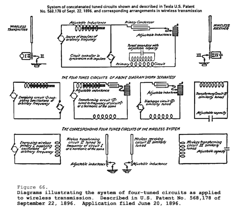
System of concatenated tuned circuits shown and described in Tesla U.S. Patent No. 568,178 of Sept. 22, 1896, and corresponding arrangements in wireless transmission.
The True Wireless, Electrical Experimenter, May, 1919.
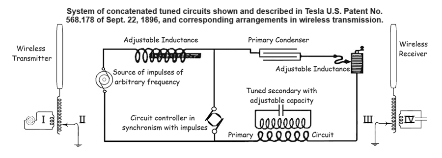
Here [Fig. 66] is something important, which I have tried to illustrate in a diagram. This diagram represents the system which I described in my patents of 1896, in which I showed four circuits in attunement, and I will endeavor to illustrate how these circuits are the exact equivalent of the wireless cicuits.
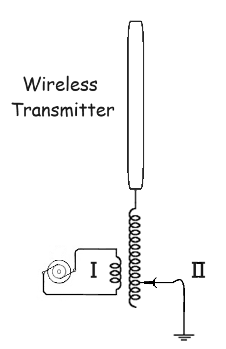
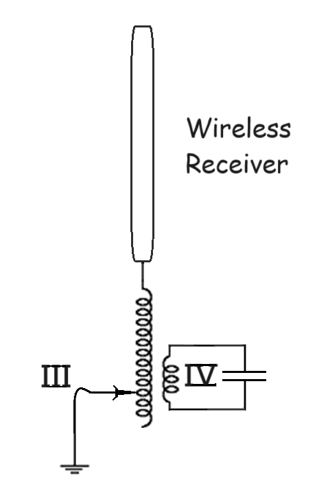
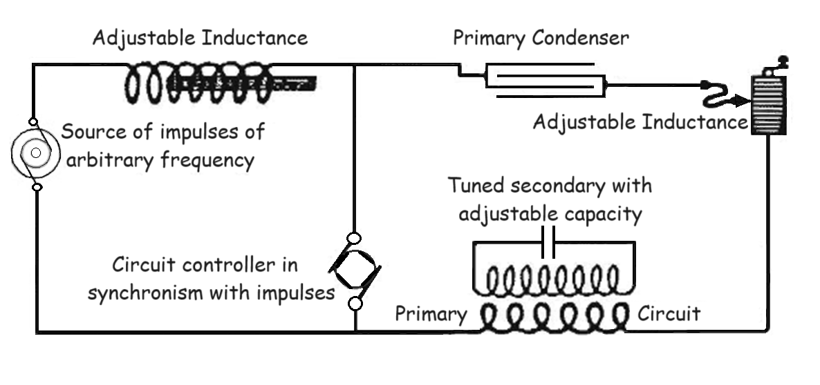
You see, here on the top I have titled, "System of concatenated tuned circuits shown and described in Tesla U.S. Patent No. 568,178 of Sept. 22, 1896, and corresponding arrangements in wireless transmission." - The first circuit which I have here is composed of a controller, a source of impulses of arbitrary frequency, and an adjustable inductance. I have drawn that circuit separately, and you see it here; that is my first circuit, "Energizing circuit supplying oscillations of arbitrary frequency I"
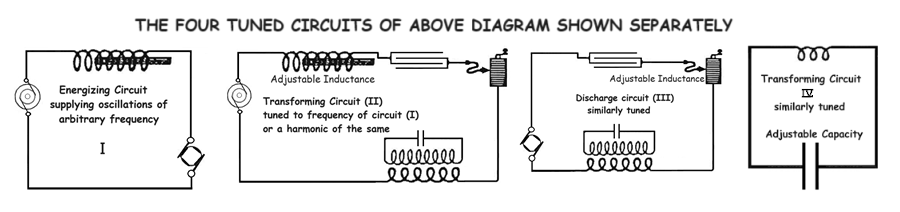
THE FOUR TUNED CIRCUITS IN THE ABOVE DIAGRAM SHOWN SEPARATELY
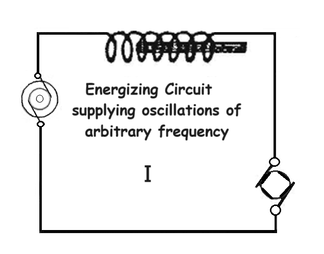
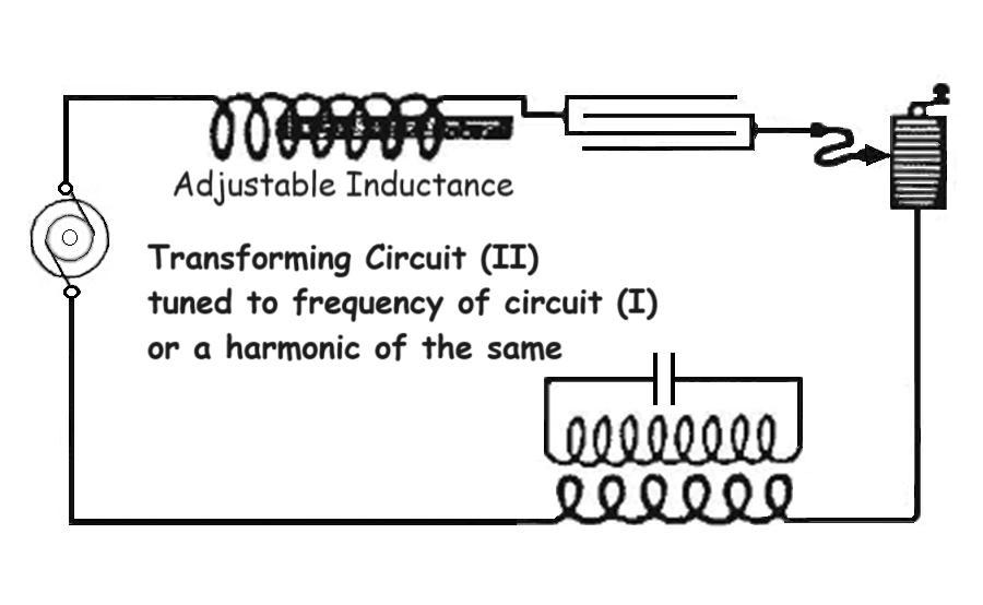
The second one is the circuit including the source, the adjustable inductance, this coil, and this primary. I have shown this circuit separately and marked it "Transforming circuit (II) tuned to the frequency of circuit (I), or a harmonic of the same."
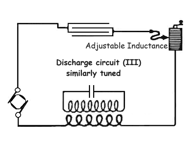
The third circuit is formed by the primary, the self-inductance, and the controller, and it is shown as "Discharge circuit (III) similarly tuned"
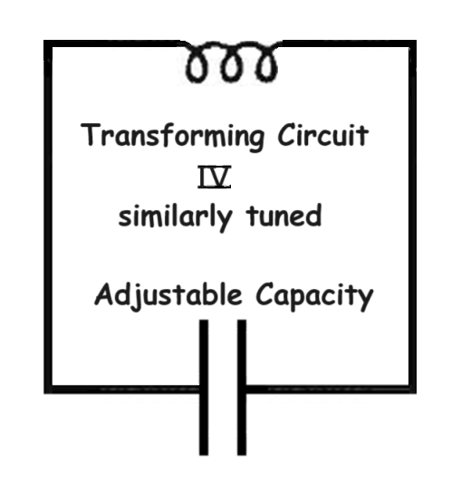
And then here is the fourth and last circuit with an adjustable capacity, shown as "Transforming circuit (IV) similarly tuned"
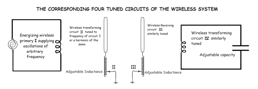
THE CORRESPONDING FOUR TUNED CIRCUITS OF THE WIRELESS SYSTEM
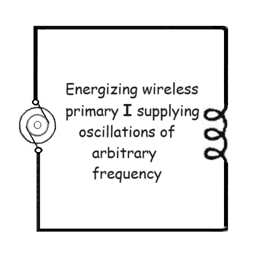
Now, if you look at wireless diagrams and bear in mind that I have, first of all, established the equivalency between two-wire and one-wire transmission, that I have then gone a step further and established the equivalency between the transmission through one wire and the transmission through the earth, which is wireless, then you will readily see that these wireless arrangements which are popular now, are merely an imitation of my arrangements, are in fact exactly the same. Here [Fig. 66 top left] is a wireless transmitter, comprising a primary circuit I, in which current impulses of arbitrary frequency are produced, corresponding to the circuit (I) in this figure.
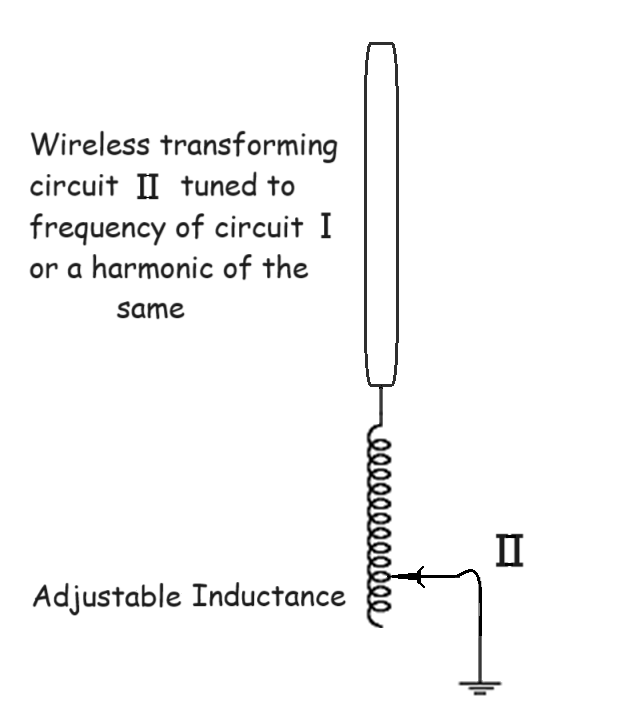
Here is the secondary tuned circuit connected to an antenna and to the ground, including an adjustable inductance, exactly as here; that is circuit II, which corresponds to this circuit (II) in my arrangement.
Then there is on the receiving side again the antenna circuit with an adjustable inductance, corresponding to my circuit (III) with the adjustable inductance and this capacity.
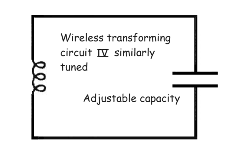
And then there is finally the fourth tuned circuit like my circuit (IV) with adjustable condenser. All is therefore a perfect, exact equivalent of the arrangements I described long ago.
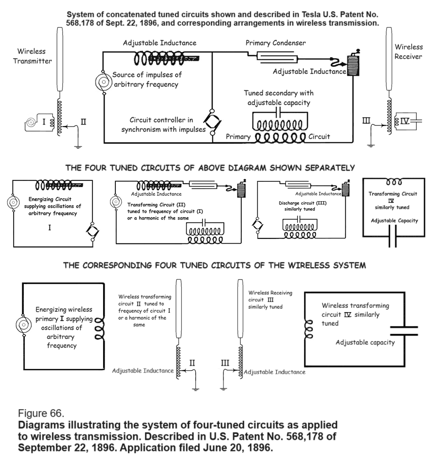
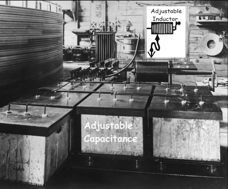
This four-circuit arrangement has been claimed by others, but they overlook that I have patented that on September 22, 1898; and more than that, they overlook the fact that my Belgian patent, showing the exact arrangement of my American patent, was issued in 1898, prior to any suggestion by Ferdinand Braun, or Marconi, or other men who have come subsequently. Therefore, if these are the facts, my statement of them cannot be interpreted as slighting my fellow workers; I point it out merely as impersonal facts, and if these men have claimed that they originated this system it was merely due to ignorance on their part.
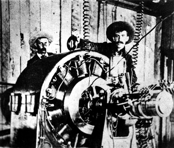
Source of impulses of arbitrary frequency (133 Hz) used to power the oscillator at Colorado Springs, above.
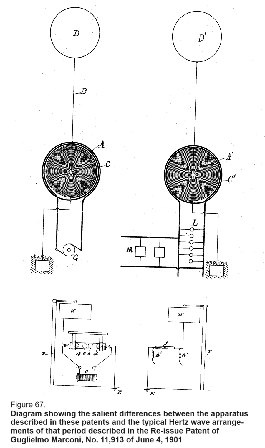
My system is a system which can be perfectly attuned, and it will transmit to this antenna, here [at right], hundreds of thousands of times, millions of times, the energy which his device can transmit to his receiver.
Furthermore, my system is a system which is exclusive, which can be tuned and rendered private; that of Marconi cannot be tuned. Moreover, his transmitter generates electromagnetic waves of very high frequency, which are absorbed in the air and only penetrate a few miles, while mine produces current waves which pass to the opposite point of the globe with the greatest facility, and can affect instruments at any distance.
If you take these two contemporaneous diagrams, and examine the subsequent developments, you will find that absolutely not a vestige, not a vestige of that apparatus of Marconi remains, and that in all the present systems there is nothing but my four-tuned circuits. Everybody is using them.
In changing this to my system, there is where the great step in wireless has been made. But, as a matter of fact this came gradually. When my experiments with the magnifying transmitter were published in the Electrical Review [New York, Mar. 29, 1899], there is where the radio men recognized the necessity or the advantage of going to lower frequency. They started out with very high frequencies, and you will hear it asserted that prior, say, to 1901, there were frequencies of 2 million used. There is no truth in that. Long before 1901 the radio men had followed my lead, and they had gradually reduced their frequencies; and when in 1900 I published these results in the Century Magazine and showed that these were obtained with a frequency of 50,000, there was a stampede for these frequencies. [T]hese frequencies have been adopted by all experts before 1901, so that there is no truth in the statement that very high frequencies had been used subsequent to that date. It was only in the very beginning that very high frequencies were employed, but they were gradually abandoned, until in 1900 everybody began to use low frequencies.
Counsel
Was this system of yours used in anything but experimental work?
Tesla
Why, there is no other system that is [emphasis in original] used. Every wireless message that has ever been transmitted to any distance has been transmitted by this apparatus; there is no other way. Mr. Marconi came here, when he announced that he had made a transmission across the Atlantic. I congratulated him. I said to my secretary,
"I cannot understand how Marconi could obtain these results. His apparatus cannot do this; he must use my apparatus."
My secretary said,
"How can Marconi use your apparatus when here is his statement that he had tried it and it did not work?"
But, when you examine the publications of a year later, you will note Marconi comes out with the statement that he had used these four circuits, and the only excuse that he has put up is that he did not know that these four circuits had to be attuned. That was his excuse. And in the meantime, he had been using this apparatus. Every message that has ever been transmitted to any distance, by telegraph or telephone -- wireless, has been by the use of these instrumentalities and no others.
Counsel
Your experimental [work], as I understand, was on a considerable scale. Describe the size and use of those experiments.
Tesla
They were only experimental in the sense that they were preparatory steps to the construction of a big plant which I undertook to erect. You see, my apparatus of 1896, exhibited in my laboratory, was sufficient to flash a message across the Atlantic; but I was preparing for a very big undertaking, and as the things then looked I was capable of putting that undertaking financially through; I had excited the interest of a great man. But, when the radio business assumed the phase of stock jobbing, that great man said to me,
"I could not touch it with a 20-foot pole,"
and there I remained stuck with my project and unable to carry it through. But, I undertook the design and construction of a plant for telephony around the world, and just as certainly as you can hear my voice across this small space, you would hear my voice across the whole globe if I had completed that plant.
Counsel
You have spoken of these stations, elsewhere, as not commercial. I spoke of your experimental stations. In what way do you use the word "commercial"?
Tesla
Why, I mean commercial in the sense that you are transmitting messages for a charge.
Counsel
These stations that you constructed -- and let us refer to your Colorado station -- was the construction and operation on a scale adapted to commercial work?
Tesla
Yes, it was not only adapted, but better adapted than any plant that has since been built. I had in my Colorado plant a current of 1,000 amperes in the antenna. The biggest radio plants today develop something like 200 or 250 amperes in the antenna. Remember, also, that my current was under a great tension. My current was under a tension of 3 1/2 or 4 million volts, others only 30,000 volts; so you can imagine the enormous difference between the energy of the vibrations which I produced and those in the present plants.
I had a capacity of 500 or 600 centimeter [i.e. 550 or 660 picofarads], but this capacity was charged to 4 million volts; they have a capacity of, maybe, 18,000 or 20,000 centimeters [i.e., 0.020 or 0.022 microfarad], whatever it is, but they charge it to only 30,000 volts. You know the energy of a system depends on the square of the potential. If I used a capacity, say, one-tenth of that and I charged that capacity to a thousand times greater potential, I have immeasurably greater energy in my system. [T]his is only possible, as I said, through the observance of the rules which I have already explained, which enable me to economize in the production of electromagnetic waves, to suppress them as much as possible, and to intensify the current which can perform work at any point of the globe.
Counsel
Going back for a moment, what was the longest distance over which there was actual radio transmission?
Tesla
I have already stated that the greatest distance that I ever transmitted was from Houston Street to West Point.
Counsel
Does that include Colorado also?
Tesla
Oh, at Colorado there was a difference. In Colorado I demonstrated --
Counsel
I do not want to get these things mixed up; are they the same thing?
Tesla
No, not the same thing. This system of [Fig. 67, upper diagram] is the system I have described.
Counsel
Was that used out in Colorado?
Tesla
Oh, the Colorado apparatus was on the same principle, but looked different.
Counsel
Referring to this [Fig. 67, upper diagram], was this used only here in New York?
Tesla
Only here in New York.
Counsel
That is what I want to get clear in my mind.
Tesla
Only here in New York, and with this apparatus exactly as described in my patent I transmitted from my laboratory on Houston Street to West Point, and that was the biggest distance that I ever transmitted.
Counsel
In the Colorado apparatus, did you have a spark gap in the transmitting set?
Tesla
Oh, I sometimes had a spark gap, but not in the antenna. The antenna circuit was always grounded without any break.
Counsel
But your oscillator there was a spark oscillator?
Tesla
Oh, sometimes, yes. But, pardon me; in my patents I described both a dynamo and my transformer, and those two things are equivalent.
Counsel
I understand that, but I am speaking about what you actually used in Colorado.
Tesla
In Colorado I used the spark gap method because I could not get from any high frequency machine any such amount of energy. That is the point. But I used damped and undamped waves -- both.
Counsel
I have read in some of your writings that you went to Colorado to further experiment with certain apparatus which you had tested to your own satisfaction at sea level. What was the reason that you went to Colorado to continue those same experiments?
Tesla
I built the Colorado experimental station preliminarily to the installment of a large plant on Long Island, which I was designing at that time. I had some friends who were willing to back me up financially, but I did not care to take the responsibility. I told them that I could do it without any further experiment but, in order to satisfy myself of everything, I preferred to go to Colorado, spend $50,000 out of my own pocket, demonstrate the proposition, and then go to the financiers who were willing to trust me and say,
"I am now prepared to build."
Counsel
I was not asking for the personal reason as much as the scientific reasons. What I wanted to get at, was that demonstration undertaken in Colorado for the purpose of getting the higher altitude of the air?
Tesla
No, it was nothing of the kind. I simply went there because in Colorado my system of power transmission was introduced. All around the plants in the mountains, my three-phase system, and the induction motors were employed. All the mines surrounding Cripple Creek and Telluride were operated by them, and I had friends there who were only too delighted to give me all the power I wanted, and not charge anything for it. And furthermore, the climate was praised up very high. Of course, when I came to Colorado Springs I discovered that 30,000 consumptive were there, out of 35,000 inhabitants. And then I made a remark, for which I was near chased out; I said that Colorado Springs was a nice place but only two kinds of people ought to go there -- those who have consumption and those who want to get it. I was nearly chased out.
My experiments [on Houston Street] showed that at a height of 5 miles the air was in conduction to transmit the energy in this way, but my experiments in Colorado showed that at a height of 1 mile it is plenty enough rarified to break down under the stress and conduct the current to the distant points.
I have to say here that when I filed the applications of September 2, 1897, for the transmission of energy in which this method was disclosed it was already clear to me that I did not need to have terminals at such high elevation, but I never have, above my signature, announced anything that I did not prove first. That is the reason why no statement of mine was ever contradicted and I do not think will be, because whenever I publish something I go through it first by experiment, then from experiment I calculate, and when I have the theory and practice meet I announce the results.
At that time I was absolutely sure that I could put up a commercial plant, if I could do nothing else but what I had done in my laboratory on Houston Street; but I had already calculated and found that I did not need great heights to apply this method. My patent says that I break down the atmosphere "at or near" the terminal. If my conducting atmosphere 2 or 3 miles above the plant, I consider this very near the terminal as compared to the distance of my receiving terminal which may be across the Pacific. That is simply an expression. I saw that I would be able to transmit power provided I could construct a certain apparatus -- and I have, as I will show you later. I have constructed and patented a form of apparatus which, with a moderate elevation of a few hundred feet, can break the air stratum down. You will then see something like an aurora borealis across the sky and the energy will go to the distant place.
That is very simple. An apparatus which permits displaceing a certain quantity of electricity in the terminal -- we shall say so many units -- will produce an electric potential at a distance of 5 mile, and the fall of electric potential per centimeter will be equal to the quantity of electricity divided by the square of the distance.
Now, I have satisfied myself that I can construct plants in which I may produce, per kilometer of the atmosphere, electric differences of of potential something like 50,000 or 60,000 volts, and at 50,000 or 60,000 volts that atmosphere must break down and will become conductive.
So that, when I had explained this principle to Lord Kelvin, he became absolutely convinced that I could do it; but Helmholtz was convinced from the very beginning that I could do it. It took argumentation, however, and demonstration by experiments, to convince Lord Kelvin.
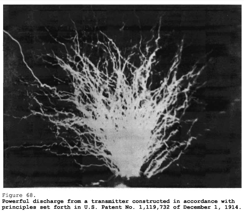
Here [Fig. 68] I have a photograph to just give you a striking illustration of some of these effects. This thing that you see here is a large ball [pointing to the bottom of the photograph], on top of a cylindrical conductor, lifted above the roof. The roof was removable made in two parts, which could be slid apart. The ball could be pushed up and down and lifted to a certain height as I needed it. The experiment shows just that kind of arrangement which I have illustrated in previous diagrams and with which I reached enormous potentials. So great was the pressure that the ball discharged into the air and I have been able to follow for a 100 feet some of these streams. That will give you an idea what a tremendous display it must have been. The current passing through this ball was about 1,000 amperes and the display, seen from a distance, was such that people might have thought the building afire, and many times they did think so.
Counsel
What was the voltage of it?
Tesla
In this experiment, the voltage might have been something like 7 or 8 million volts, but I want to tell you, though, that I am referring to the maximum potential. The moment you get these enormous streamers the potential drops. I mean that was the breaking potential.
Counsel
You had to store the energy in the condenser for a certain length of time and then let it out all at once?
Tesla
Yes, that is a natural process -- in a small interval of time.
Counsel
You could not have kept this display up merely from the energy of the alternator itself?
Tesla
No, sir, I could not have kept that energy up, but I will tell you the secret of all these wonderful displays. It is now perfectly well understood, but at the time when I did this work it was not understood. Consider a gun, for instance, a large gun which hurls a projectile of a ton a distance of 18 or 20 miles. There is a German gun now that fires at 28 miles. If you figure the horsepower at which guns deliver energy, you will find that it amounts to from 6 to 12 or 15 million horsepower. That is, the biggest gun may develop energy at the rate of something like 15 million horsepower, if my recollection of calculations I made is correct. With the methods I devised, with my transformer, it is not at alldifficult to get rates of energy many times that, and I have, for instance, figured that in the plant on Long Island, which I put up, under certain conditions, if I wanted to operate, I could have just reached a rate of 1 billion horsepower.
That wonderful thing can be accomplished through a condenser. The condenser is the most wonderful electrical instrument, as I have stated before. You store less energy in the condenser than in the gun but, whereas a gun will discharge the projectile with a velocity of 2,000 feet per second, which means that the energy is delivered in, say, 1/50 of a second, a condenser can discharge the energy in 1 millionth of this time. Thus, if you store in the condenser energy at the rate of 100 kilowatts, and then discharge it in oscillations of 250,000 per second, it means that you have to multiply these 100 kilowatts with 1 million; therefore, you have a 100 million kilowatt rate as the current discharges. So, all these effects which were produced, and which elicited, of course, great wonderment of the profession, were always produced by damped waves, because with the undamped waves it would not have been possible to attain any such activities.
In the plant in Colorado, my problem was to learn how to construct the apparatus and how to handle these enormous forces which it was necessary to control in a big industrial plant. In these effects, I took a scientific interest and these photographs were intended to show to the world that it was not a dream, what I was doing. That was the sole purpose, but I would not do that in a commercial plant. It was simply to show the marvelous power that could be developed with the apparatus I had perfected.
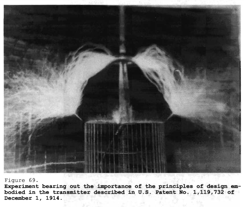
I thought that with a few photographs of this kind [Fig. 69] I would throw light on the apparatus. Here, you see [top center], is a cylindrical antenna. This antenna was put up in 1899 and was a landmark for several years. Everybody has seen it. Therefore, when I am told that other people have used cylindrical antennae before, that cannot be true because I have done that in 1899 -- always in public and everybody has seen it.
As you see, this bit of curve behind, that is my self-induction in series with the antenna, which generates this alternating force, and there is another self-induction coil, and the whole circuit tuned to resonance. The antenna is not connected now. That is a perfectly insulated capacity, but the current passes into it, leaping through a great distance, something like 12 or 15 feet, with a tremendous display on both sides.
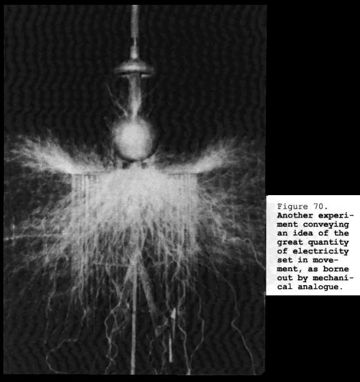
This [Fig. 70] was illustrated and explained in my article in the Century Magazine of June 1900, page 191. This is an experiment which is wonderful, and I want you to understand its meaning. Here I have a ball, a very large ball, connected to the circuit.
Counsel
That is made of what?
Tesla
This ball is of wood, covered with metal, because the electricity does not go into it, and it does not get hot, so it is perfectly safe to employ wood. Around here is a bent 2-inch pipe -- a bare pipe. I put it there because if I did not do so my insulation would immediately catch fire; therefore, I had to protect it. In this experiment there is a distance of about 60 feet from here to there [*], and through this pipe electricity escapes into the air.
To explain this phenomenon, imagine, presently, that you had a big water main, say a main that supplies the city, and on that main a gate valve, and before that valve a reservoir which could stand a great pressure. Suppose that you turn the pressure on this main and that the water cannot flow out; then there will be full pressure on that reservoir, but if you open the valve wide, the moment it is opened the pressure will go down to nothing if the main is large. Therefore, in the reservoir before the valve, there will be no pressure. Here is the electrical main. This pipe [Fig. 70], out of which the electricity escapes in a powerful stream, is the open water main -- a large main through which the water can freely flow out. This ball here is the reservoir on the end of the pipe, a reservoir which can stand a tremendous pressure, and notwithstanding that this main is open, and that all the electricity, probably 800 amperes, can flow out readily, nevertheless the pressure on the open main is so great that this reservoir bursts under the stress and you see streams coming out of the ball. That is a wonderful thing. It shows the volume of the discharge.
Counsel
Has that any relation to the aurora borealis effect that you referred to awhile back?
Tesla
No, sir; not at all. This is simply a scientific experiment.
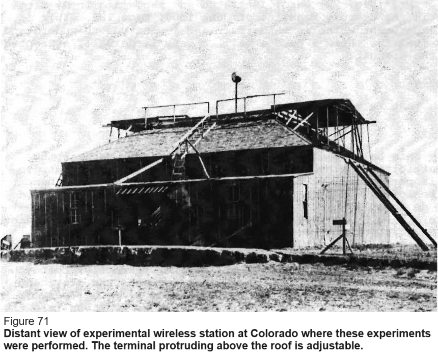
There [Fig. 71] is a view from a distance of my plant at Colorado Springs. You see here the removable roof, through which I could pull this capacity up and down. There is a pipe of 8 inches in diameter, and on top of it is a ball. That was my capacity. That is the capacity from which you have seen the streamers come out in one of the previous photographs [Fig. 68].
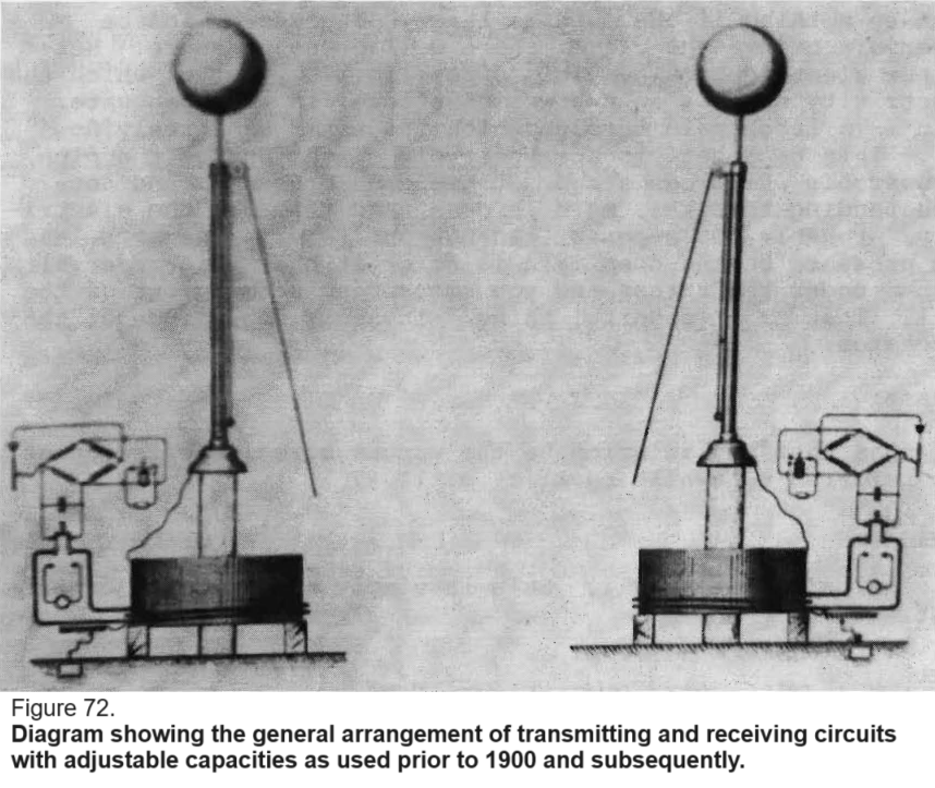
This [Fig. 72] is simply intended to show how I operated these adjustable capacities. Here is a pipe, and a ball on top of it, an arrangement of a transmitter and receiver. These capacities lifted up and adjusted. This is a drawing of 1897 or 1896, possibly.
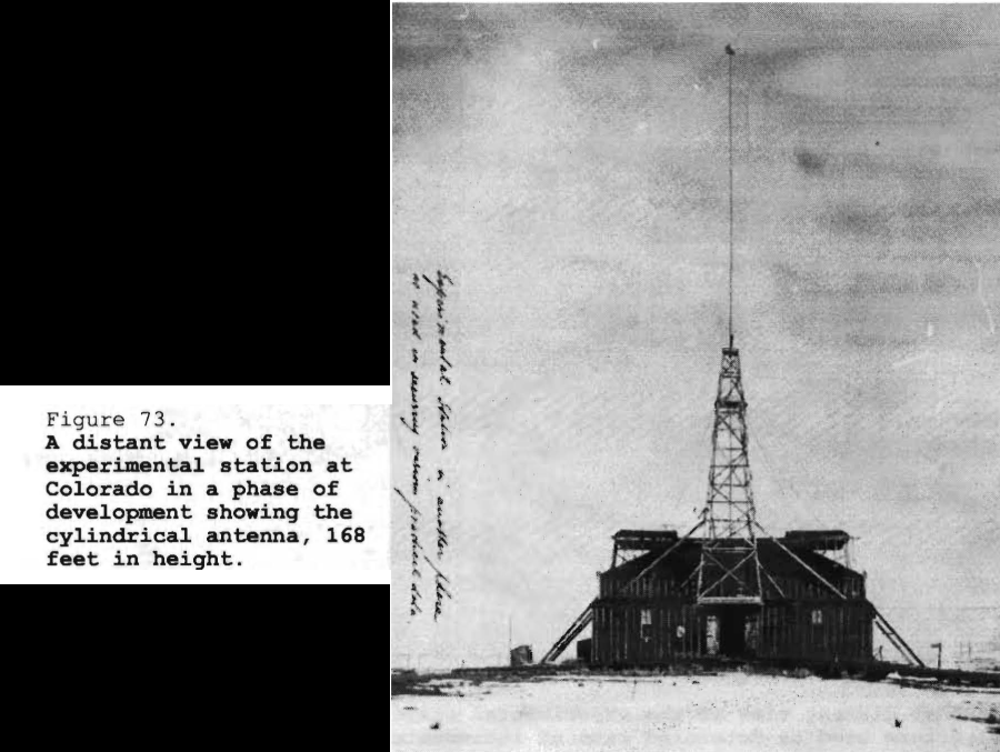
Here [Fig. 73] is another view from a distance. This is the cylindrical antenna reaching a height of 168 feet.
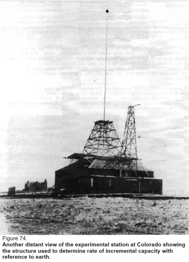
I take the liberty of pointing to this little structure on the side [Fig. 74 shorter mast at right]. [Note] this ball suspended here. That is just an experiment which I was making in the measurement of capacity, determining the rate of increment of the capacity with reference to the earth.
Counsel
When was that put up in that form? Does that represent some change over the earlier photograph?
Tesla
No, it does not represent change. It represents simply various steps in my experiments. As I proceeded in my investigations, I was gradually increasing the antenna and studying the effects I was getting, but I always remained true to the principal to arrange my conductors on a radius of large curvature so as to enable me to work up very high potentials with low surface densities. Now, for instance, you will find illustrated in patents cylindrical structures of wires. I know of an illustration showing a cylindrical antenna made up of wires, but when I figure the density of distributed charge I find that it was an ozonator; it was not an antenna such as my own. It generated ozone. The densities on this thing were enormous, even with low potentials. I have kept my large curvatures, my large surface, so that nowhere would I get an excessive density. Nevertheless at night, this antenna, when I turned on the full current, was illuminated all over and it was a marvelous sight.
Counsel
When you used the higher potentials?
Tesla
Yes.
Counsel
This was a column you say 168 feet high?
Tesla
Yes.
Counsel
And the diameter of that column was what?
Tesla
I think the first pipe was 10 or 11 inches, and then it gradually diminished in a few sections.
Counsel
And the size of the ball on top?
Tesla
The ball on the top [was], I think, 32 inches [in diameter].
Counsel
What was the column itself made of?
Tesla
Ordinary iron pipes.
Counsel
Wrought iron pipes?
Tesla
Wrought iron pipes, yes.
Counsel
What was the ball made of?
Tesla
The ball was of wood covered with metal.
Counsel
And the column was insulated with what from the ground?
Tesla
That was supported on a special tree of fir. I went to the lumber men and tried various woods and could not find anything until I discovered a magnificent piece of a certain kind of fir. I took samples, tested them, and found that they were very highly insulating. I tested the fiber and found it was prodigiously strong and amply sufficient support the antenna. As a matter of fact, it carried it for 4 years.
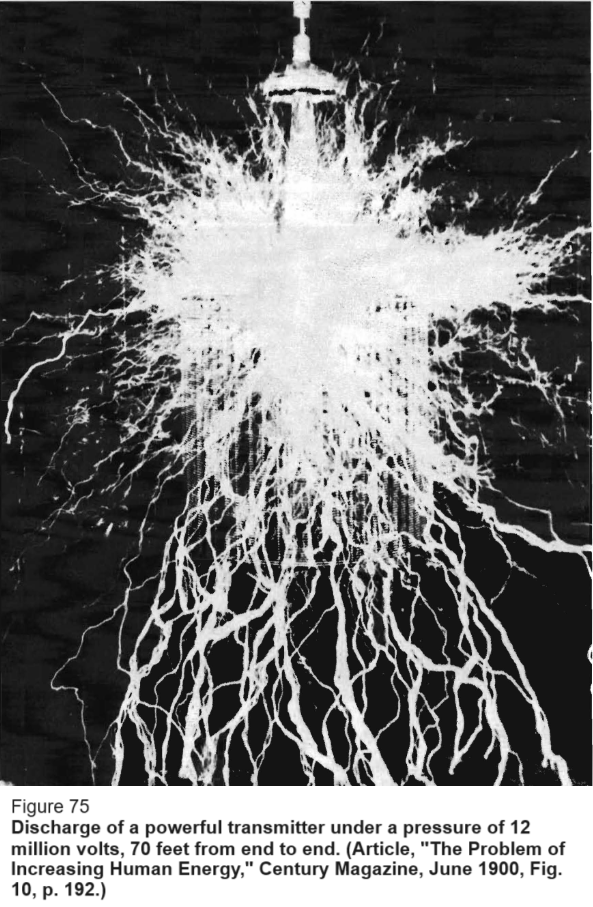
Counsel
When was it completed in this case?
Tesla
In November -- probably late November, 1899.
That photograph [Fig. 75] is illustrated in my article in the Century Magazine of June 1900, and it shows a remarkable display. When I sent these photographs to such men as Lord Kelvin, Sir William Crookes, Sir James Dewar, Roentgen, Lenard, Slaby, and others, some of them cabled me expressing their wonderment at how I produced these effects.
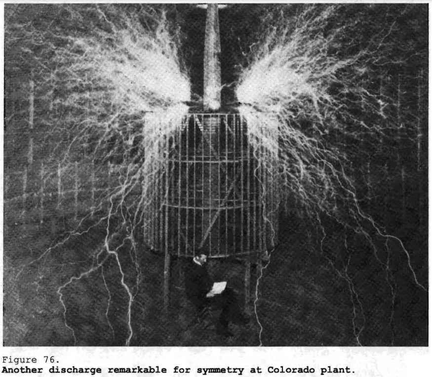
Here [Fig. 76] is another one. There is the fir tree which I obtained, and on top of it is the antenna peculiarly supported; namely, as it is explained in one of my patents. It is imperative to support a system of that kind on places of low electrical density. If I do not support it on places of low electrical density, then the first thing that will happen will be surface conduction enabling the current to flow to earth, and before one knows the antenna will be grounded and everything destroyed. But, by providing a sort of roof, I get on the under side a support on which the electrical density is nothing, and then the support is absolutely safe, even in rain, because it keeps dry, and it is always in contact with a conducting surface of low electric density.
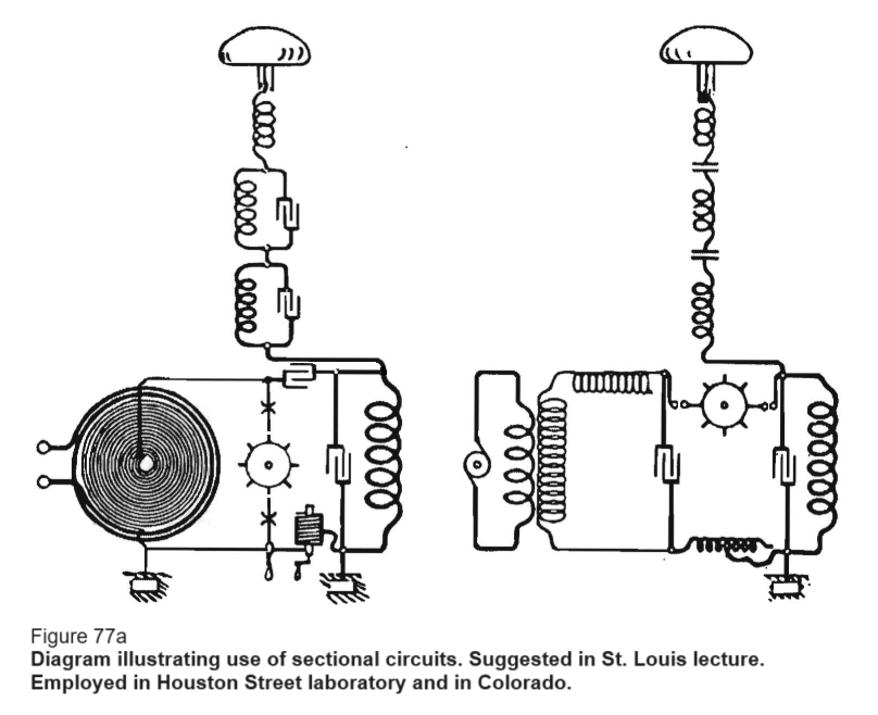
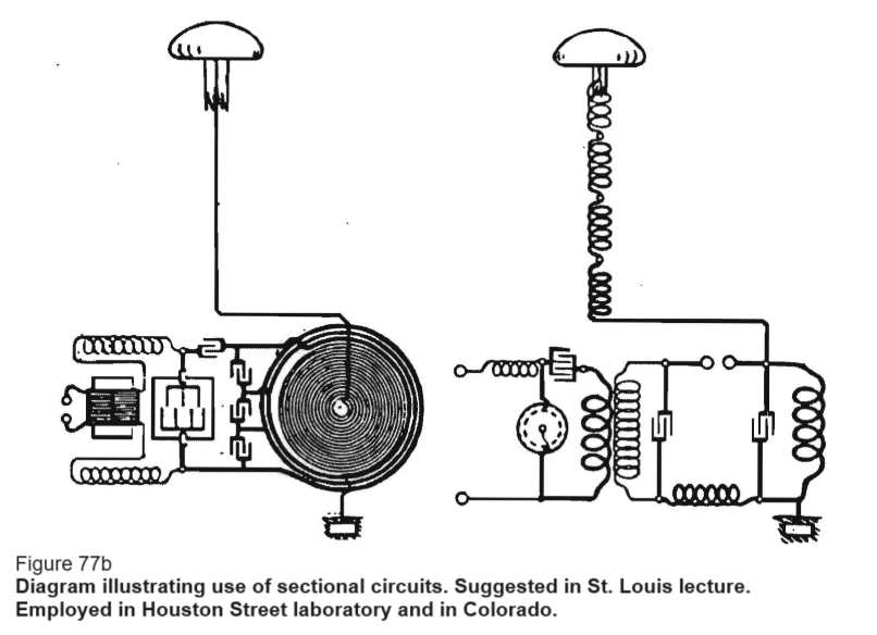
There [Fig. 77a and Fig. 77b] is another improvement which I carried out in the laboraories on South Fifth Avenue and Houston Street, and which I also employed in Colorado. That is, the employment of sectional circuits. I had sometimes as many as 20 of these sections. There are specific results which can be obtained with these sectional circuits, but the technical literature is full of illustrations which are erroneous, showing apparatus that clearly could not work. That is a special subject on which I have spent a great deal of time, and in this short account of this work I can do no more than just say that these various sections are tuned either to the same or to different frequencies. I sometimes tuned them to compound frequencies and then worked with the fundamental tone, corresponding to the Fourier harmonic. Professor Stone has also done a great deal of work in that direction. I do not know who of us would be prior in records.
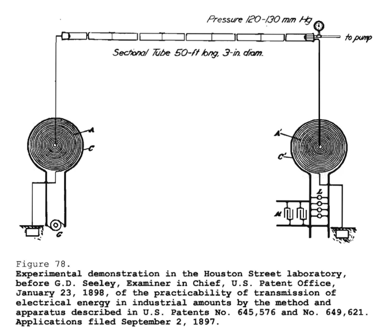
Tesla
This [Fig. 78] is a diagram representing the arrangement of apparatus as in a practical experiment which I performed before G.D. Seeley, Examiner in Chief, U.S. Patent Office, on the 23rd of January, 1898. This experiment illustrates a great departure I had made a little prior to that date. Up to the end of 1896, I had been developing the wireless system along the lines set forth in my lecture which is in the Martin book, particularly in the chapter on Electrical Resonance, pages 340-349. As I stated then, if that plan of mine was practicable, distance meant absolutely nothing; distance merely came into consideration when you flashed rays, electromagnetic or Hertzian waves, or some agency of that kind. By the plan I had conceived, if it was realizable, it was just as easy to telegraph or telephone across the entire globe as it is across this room.
Developing along these lines, my effort was first to have the biggest possible capacity because I had shown that, theoretically, the effect would be dependent upon the quantity of electricity displaced. The quantity of electricity displaced is proportionate to the capacity. Therefore, in order to realize my scheme, it seemed necessary to employ the biggest possible capacities that could be practically constructed; that was my idea at the beginning.
But I knew also that even with a big capacity, if I connected it to the ground, through a generator, there still would be a frequency high enough to cause a considerable loss of energy in the production of the Hertz or electromagnetic waves; consequently, I had to employ also a very large inductance. Thus, my system was based on the proposition that I employ a very large inductance and a very large capacity and, furthermore, that I raise the potential of the source so high, by resonance, as to displace a quantity of electricity big enough to affect sensibly not only the near portions of the globe, a distance of 100 miles or so, but the whole globe.
In [my] Houston Street laboratory, I had already satisfied myself that it could be done. But in experimenting with these high potential discharges which I was always producing, I discovered a wonderful thing. I found, namely, that the air, which had been behaving before like an insulator, suddenly became like a conductor; that is, when subjected to these great electrical stresses, it broke down and I obtained discharges which were not accountable for by the theory that the air was an insulator. When I calculated the effects, I concluded that this must be due to the potential gradient at a distance from the electrified body, and subsequently I came to the conviction that it would be ultimately possible, without any elevated antenna -- with very small elevation -- to break down the upper stratum of the air and transmit the current by conduction.
Having discovered that, I established conditions under which I might operate in putting up a practical commercial plant. When the matter came up in the patents before the Examiner, I arranged this experiment [shown in Fig. 78] for him in my Houston Street laboratory.
I took a tube 50 feet long, in which I established conditions such as would exist in the atmosphere at a height of about 4 1/2 miles, a height which could be reached in a commercial enterprise, because we have mountains that are 5 miles high; and, furthermore, in the mountainous regions we have often great water power, so that the project of transmitting it, if the plan was rational, would be practicable.
Then, on the basis of the results I had already obtained, I established those conditions, practically, in my laboratory. I used that coil which is shown in my patent application of September 2, 1897 (Patent No. 645,576 of March 20, 1900), the primary as described, the receiving circuit, and lamps in the secondary transforming circuit, exactly as illustrated there. And when I turned on the current, I showed that through a stratum of air at a pressure of 135 millimeters, when my four circuits were tuned, several incandescent lamps were lighted.
Counsel
What did you use as the source of energy in your primary transmitting circuit, at the time you demonstrated this apparatus to Examiner Seeley?
Tesla
I used a break, a mechanically rotating break, which was charging a condenser 5,000 times a second as I described in my patent Number 645,576 of March 20, 1900.
Counsel
What was the voltage that was generated?
Tesla
The voltage was about 4 million volts.
Counsel
You say you used a break, which I understand to be a rotary spark gap. What was the original source of power?
Tesla
The original source of power was an alternator which I regularly employed there, from which I could get about 30 horsepower in ordinary experimentation. It was a machine of a frequency of about 60 cycles.
Counsel
And that was connected in circuit with the condenser and a gap in the well known way of your oscillators?
Tesla
Yes.
Counsel
Then you got from that, by means of a rotary gap, about 5,000 sparks?
Tesla
Yes, 5,000 per second and I transferred [these] to a frequency of 200,000 to 250,000 per second. Pardon me for saying, I had arranged for the Examiner to make this demonstration with a high-frequency alternator; but just as the work was pressing I tried it and could not get the necessary tension with it, otherwise I would have used the alternator. But in this other way, I could the 4 million volts I needed; that is the reason why the experiment was made with this kind of apparatus.
Counsel
And you had a wave frequency of what?
Tesla
Between 200,000 and 250,000. That was simply wave frequency; that did not mean anything here because I was transmitting through a conductor. I was not radiating energy into space.
Counsel
Was that a glass tube?
Tesla
Yes, 2 or 3 inches in diameter, and joined with rubber. Then there was a pipe that led to the pump, and I had a manometer to show accurately the pressure in the tube. I calculated it so that it corresponded to a definite height of about 5 miles. Because I had mentioned in my patent 5 miles, I did not want to retract that statement. It was simply to show that this was practicable.
We shall come imediately to something which will put all this in a different light.
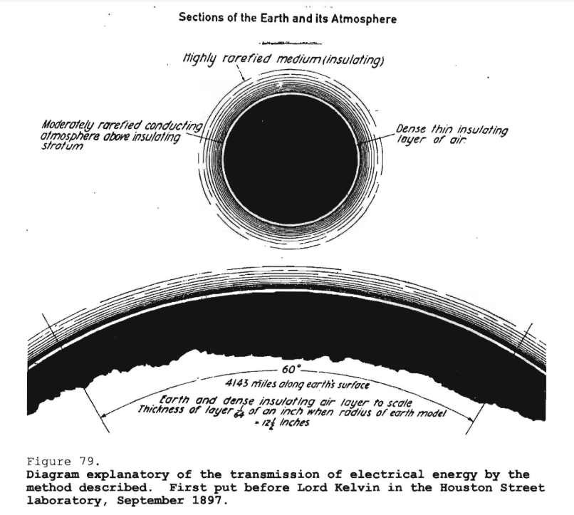
Here [referring to Fig. 79] is the earth. Radio engineers do not realize this truth, but when they do they will immediately get a different view of the whole radio transmission and will design their apparatus accordingly. [I]n fact, they will do exactly what I did. It was a revelation to me.
The earth is 4,000 miles radius. Around this conducting earth is an atmosphere. The earth is a conductor; the atmosphere above is a conductor, only there is a little stratum between the conducting atmosphere and the conducting earth which is insulating. Now, on the basis of my experiments in my laboratory on Houston Street, the insulating layer of air, which separates the conducting layer of air from the conducting surface of the earth, is shown to scale as you see it here. Those [radii lines] are 60° of the circumference of the earth, and you may notice that faint white line, a little bit of a crack, that extends between those two conductors. Now, you realize right away that if you set up differences of potential at one point, say, you will create in the media corresponding fluctuations of potential. But, since the distance from the earth's surface to the conducting atmosphere is minute, as compared with the distance of the receiver at 4,000 miles, say, you can readily see that the energy cannot travel along this curve and get there, but these currents will travel like currents over a wire with a return. The energy will be recovered in the circuit, not by a beam that passes along this curve and is reflected and absorbed, because such a thing is impossible, but it will travel by conduction and will be recovered in this [emphasis in original] way. Had I drawn this white line to scale on the basis of my Colorado experiments, it would have been so thin that you would have to use a magnifying glass to see it.
Counsel
Will you pardon me for interrupting again. You spoke some time ago about getting all of the energy from your transmitting into your receiving station by this method of yours. I do not understand how you can get all of it.
Tesla
Oh, that is hardly true; I am speaking as a matter of principle. You never can get all the energy, because there is no such thing as perfect apparatus.
Counsel
I did not mean it in that sense. I understand that there is, of course, always some loss, but my conception was that when you created the disturbance in the electrical condition of the earth at your transmitting station, that that extended out in all radial directions.
Tesla
Yes, it did.
Counsel
And therefore how, at any given station, can you get more than a very small fraction of that energy?
Tesla
Pardon me, you are mistaken.
Counsel
That is what I want you to explain. I must be mistaken, because my conception does not fit in with your statements.
Tesla
All right, I will explain that.
In my first efforts, of course I simply contemplated to disturb effectively the earth, sufficiently to operate instruments. Well, you know you must first learn how to walk before you can fly. As I perfected my apparatus, I saw clearly that
I can recover, of that energy which goes in all directions, a large amount, for the simple reason that in the system I have devised once that current got into the earth it had no chance of escaping, because my frequency was low; hence, the electromagnetic radiation was low. The potential, the electric potential, is like temperature. We might as well call potential electric temperature. The earth is a vast body. The potential differences in the earth are small, radiation is very small. Therefore, if I pass my current into the earth, the energy of the current is stored there as electromagnetic momentum of vibrations and is not consumed until I put a receiver at a distance, when it will begin to draw the energy and it will go to that point and nowhere else.
Counsel
Why is that, on your theory?
Tesla
I will explain it by analogue.
Suppose that the earth were an elastic filled with bag filled with water. My transmitter is equivalent to a pump. I put it on a point of the globe, and work my little piston so as to create a disturbance of that water. If the piston moves slowly, so that the time is long enough for the disturbance to spread over the globe, then what will be the result of my working this pump? The result will be that the bag will expand and contract rhythmically with the motions of the piston, you see. So that, at any point of that bag, there will be a rhythmical movement due to the pulsations of the pump.
That is only, however, when the period is long. If I were to work this pump very rapidly, then I would create impulses, and the ripples would spread in circles over the surface of the globe. The globe will no longer expand and contract in its entirety, but it will be subject to these outgoing rippling waves.
Remember, now, that the water is incompressible, that the bag is perfectly elastic, that there are no hysteretic losses in the bag due to these expansions and contractions; and remember also, that there is a vacuum, in infinite space, so that the energy cannot be lost in waves of sound. Then, if I put at a distant point another little pump, and tune it to the rhythmical pulses of the pump at the central plant, I will excite strong vibrations and will recover power from them, sufficient to a operate a receiver. But, if I have no pump there to receive these oscillations, if there is nowhere a place where this elastic energy is transferred into frictional energy (we always use in our devices frictional energy -- everything is lost through friction), then there is no loss, and if I have a plant of 1,000 horsepower and I operate it to full capacity, that plant does not take power, it runs idle, exactly as the plant at Niagara. If I do not put any motors or any lamps on the circuit, the plant runs idle. There is a 5,000 horsepower turbine going, but no power is supplied to the turbine except such power as is necessary to overcome the frictional losses.
Now the vast difference between the scheme of radio engineers and my scheme is this. If you generate electromagnetic waves with a plant of 1,000 horsepower, you are using 1,000 horsepower right along -- whether there is any receiving being done or not. You to supply this 1,000 horsepower, exactly as you have to supply coal to keep your stove going, or else no heat goes out. That is the vast difference. In my case, I conserve the energy; other case, the energy is all lost.
Counsel
Mr. Tesla, does that not presuppose that the fluid must be incompressible?
Tesla
I should say so, and electricity, whatever it is, certainly it is incompressible because all our experiments show that.
Counsel
Now, if you were giving that a name, what principle would you say was involved by which the radiation loss, where there is no receiver, becomes a gain or a conservation where there is a receiver?
Tesla
There is no radiation in this case. You see, the apparatus which I devised was an apparatus enabling one to produce tremendous differences of potential and currents in an antenna circuit. These requirements must be fulfilled, whether you transmit by currents of conduction, or whether you transmit by electromagnetic waves. You want high potential currents, you want a great amount of vibratory energy; but you can graduate this vibratory energy. By proper design and choice of wave lengths, you can arrange it so that you get, for instance, 5 percent in these electromagnetic waves and 95 percent in the current that goes through the earth. That is what I am doing. Or, you can get, as these radio men, 95 percent in the energy of electromagnetic waves and only 5 percent in the energy of the current. Then you are wondering why you do not get good results. I know why I do not get good results in that way. The apparatus is suitable for one or the other method. I am not producing radiation in my system; I am supressing electromagnetic waves. But, on the other hand, my apparatus can be used effectively with electromagnetic waves. The apparatus has nothing to do with this new method except that it is the only means to practice it. So that in my system, you should free yourself of the idea that there is radiation, that energy is radiated. It is not radiated; it is conserved.
Counsel
Right in that connecting, and to illustrate your theory, I would like to know whether you consider that the radiation from any wireless station is wasted or conserved, or whether the effect produced by any of them today is due to this conductive action, so far as it is effective.
Tesla
Absolutely -- the effect at a distance is due to the current energy that flows through the surface layers of the earth. That has already been mathematically shown, really, by Sommerfeld. [See Nonradiation condition] He agrees on this theory; but as far as I am concerned that is positively demonstrated. For instance, take the Sayville antenna. Professor Zenneck took me out and gave me the particulars. I went over the calculations and found that at 36 kilowatts they were radiating 9 kilowatts in electromagnetic wave energy. They had, therefore, only 25 percent of the whole energy in these waves, and I told Professor Zenneck that this energy is of no effect -- that they produce, by the current, differences of potential in the earth, and these differences of potential are felt in Germany and affect the receiver; but the electromagnetic waves get a little beyond Long Island and are lost.
I have an idea that [you] will get the best picture of the process in my system of transmission if you will imagine that the earth is a reservoir, say, of fluid under pressure -- that is the potential energy -- and at my plant, operating a distant tuned circuit, I must open a valve and enable that energy to flow in. It is exactly that way. The energy is all conserved, whether it is vibrating or purely potential. Whatever the transmitter does in the receiver, the effect is simply to open a valve, as it were, and permit energy to flow in.
Now of course, the hardest thing to understand, if one is not a specialist in that line and has not spent years, as I have, in experiments and thought in that direction, is how can a plant like that be economically operated when we know that there are mountain peaks everywhere? Those peaks are antennae; they are likewise charged. Well, it took me a long me a long time to find that out. To give you an idea, let us take a big, enormous mountain like the peak of Tenerife. That is a big mountain that rises out of the sea and goes up to 17,000 or 18,000 feet. Naturally, that is a tremendous antenna, everybody will think. Without calculating, without passing through the experience I have gone through, you will say that peak alone will take away more energy than all the antennae you can put up all over the world. That is not so.
The peak of Tenerife has no more capacity than like 100 centimeters [110 picofarads], and it will charged to a very potential, whereas my antenna could be charged to a very high potential. I can show that the mountain would not absorb much energy, not 0.0001 percent of that my antenna would. I could put my antenna right close to the peak, and it will take 10,000 times more energy.
You must simply realize that the earth is, so far as it is mechanically looked upon, like a rough ball: but when you look at it electrically, it is a polished ball. Lord Kelvin has already in his papers on atmospheric electricity, of which he kindly sent me two copies -- he did not stop at sending me one -- grasped that; he considered the distribution of electricity on the globe, and came to the conclusion that the capacity of definite terrestrial areas does not increase sensibly with elevation.
You see, the electrical surface density on the highest peaks is not any more than just a fraction of 1 percent greater than on the sea. So that the whole thing, to my mind, appears as a wonderfully providential arrangement, and we can by this means realize thingd so marvelous that one would be almost afraid to talk about them: and the apparatus -- I do not say that because I am inventor -- the apparatus is practically the of Lamp of Aladdin.
Counsel
Is it because the earth is this inelastic mass of electricity that it is the basis for your statement that distance is of no consequence? That is the way I visualize that it is, that if the earth is an inelastic mass or body of electricity, and you set that mass into vibration at any one point, that vibration will extend to the antipodes equally as well as it will to a distance of 200 miles. Is that what you had mind?
Tesla
I must first clear away some illusionary ideas. You must first understand certain things. Consider, for instance, the term "resistance." When you think of resistance you imagine naturally, that you have a long, thin conductor; but remember that while resistance is directly proportionate to length, it is inversely proportionate to the section. It is a quality that depends on a ratio. If you take a small sphere of the same size of a pea, and compare its length with its section, you would find a certain resistance. Now you extend this pea to the size of the earth, and what is going to happen?
While the length increases, say a thousand times or a million times, the section increases with the square of the linear dimensions, so that the bigger this thing is the less resistance it has. Indeed, if the earth were as big as the sun we would still be better off than we are; we could readily telephone from one end of the sun to the other by the system, and the larger the planet the better it would be.
Counsel
Then do I get your idea correctly, that distance is of no importance because of the low resistance due to the large section of the earth?
Tesla
No, pardon me.
Counsel
I cannot quite get that. Why is it that with your system distance cuts no figure?
Tesla
Distance cuts no figure for the reason that there is no fall of potential. Now imagine this: Suppose that the earth, in reality, were a big main, a main of copper, say, that all the copper of the earth would be fused into a big main, and then you will readily see it would not make any difference where you tapped that energy, whether you do it nearby or whether you go 100 miles further, because the resistance of the main is nothing. The resistance of the earth does not come in in this way, but in another way.
These questions are very complex. The resistance is only at the point where you get into the earth with your current. The rest is nothing. Those things will be very difficult to explain without a lot of theoretical stuff, which would be unprofitable, when it is here the object to give a clear idea of the principal and nothing else.
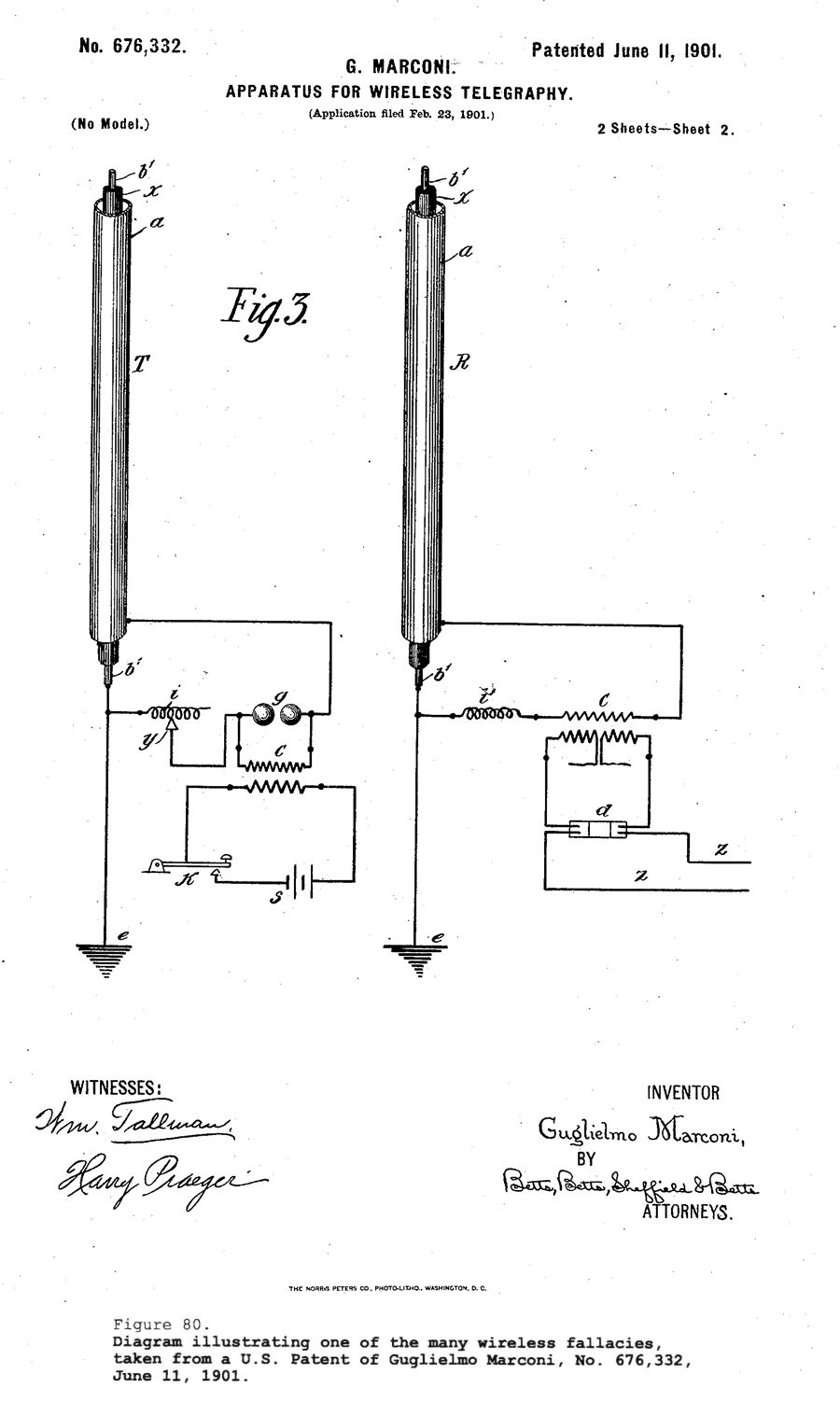
This [Fig. 80] illustrates one of the fallacies which the questioning has already brought out. Here is, for instance, an attempt to produce a large capacity, an antenna of very large capacity, by using two concentric cylinders. I have already elucidated this error, but in a different phase. The capacity between those two conductors has absolutely nothing to do with the capacity which enters into the transmission of the energy to a distance. That is purely and entirely a local flux, simply a means of wasting energy. Such errors as this you will find throughout all the technical literature, but this has already been explained in another way.
[Summarizing,] I have already explained the various steps I have set forth in the introduction to this long talk. I have explained how I produced the apparatus giving the requisite oscillations; the second step how I transformed those oscillations into vibratory energy capable of going to a distance; and, furthermore, how I solved another problem, namely, that of the right wavelengths which are effective in the conduction of energy to a distance.
Before I went to Colorado, the one thing which I needed to find out was, how does the current flow through the earth? In my experiments from Houston Street and around New York, I had already learned that the effect is proportionate to the quantity of electricity displaced, and I was in the position to accurately calculate a plant for transmission, for instance, across the Pacific or Atlantic. Those were simple problems; but I could not yet tell how the current passes through the earth, and until I could do that I could not undertake the design of a plant in all these particulars so that it could be a piece of engineering.
I spent 30 years of my work in the design of machinery of all kinds, and have never yet designed a machine which did not do as I expected, and I cannot imagine why it should not because when one calculates the things out on the basis of experimental data, the machine has to work as intended. This is engineering.
Therefore, when my friends offered to back me up for a plant under my patents, I though it was best to devote some time to an investigation, to find out what I needed, in order to have all my data accurately and guarantee that the plant would work.
The law which I discovered in Colorado is wonderful, and it shows that results undreamed of before and of incalculable moment will be obtained as soon as a plant, embodying these principles, is established on a large scale.
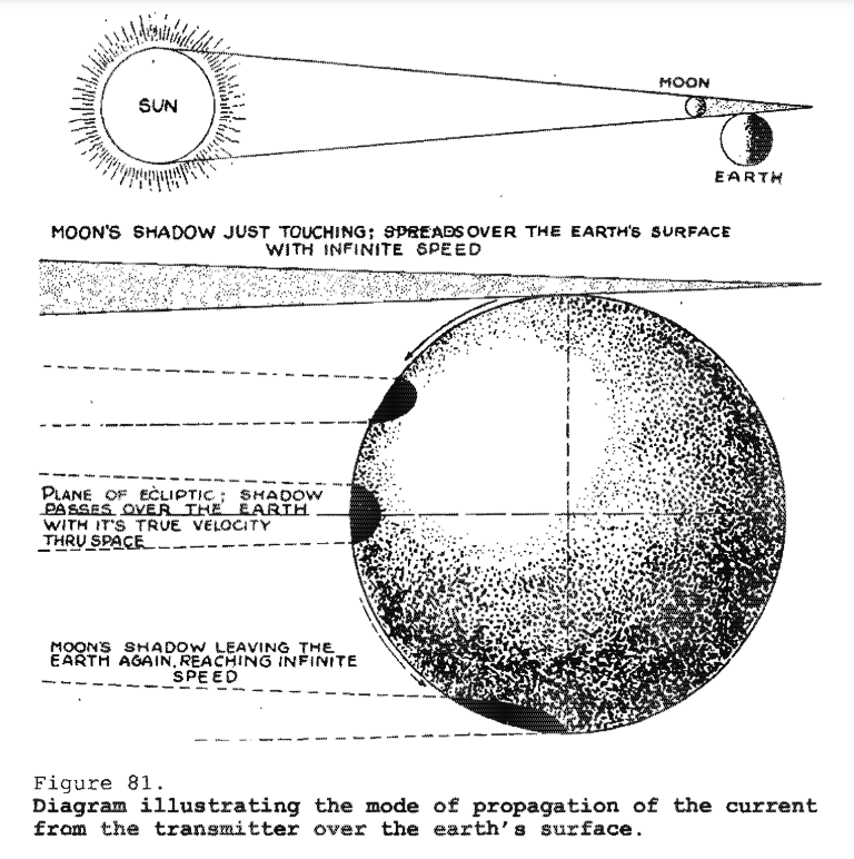
To give you an idea, I have prepared a diagram [Fig. 81] illustrating an analogue which will clearly show how the current passes through the globe. You know that in a solar eclipse the moon comes between the sun and the earth, and that its shadow is projected upon the earth's surface. Evidently, in a given moment, the shadow will just touch at a mathematical point, the earth, assuming as it to be a sphere.
Let us imagine that my transmitter is located at this point, and that the current generated by it now passes through the earth. It does not pass through the earth in the ordinary acceptance of the term, it only penetrates to a certain depth according to the frequency. Most of it goes on the surface, but with frequencies such as I employ, it will dive a few miles below. It can be mathematically shown that it is immaterial how it passes; the aggregate effect of these currents is as if the whole current passes from the transmittter, which I call the pole, to the opposite point, which I call the anti-pode.
Assume, then, that here is the transmitter, and imagine that this is the surface of the sea, and that now comes the shadow of the moon and touches, on a mathematical point, the calm ocean. You can readily see that as the surface of the water, owing to the enormous radius of the earth, is nearly a plane, that point where the shadow falls will immediately, on the slightest motion of the shadow downward, enlarge the circle at a terrific rate, and it can be shown mathematically that this rate is infinite. In other words, this half-circle on this side will fly over the globe as the shadow goes down; will first start at infinite velocity to enlarge, and then slower and slower and slower, and as the moon's shadow goes further and further and further, it will get slower and slower until, finally, when the three bodies are on the plane of the ecliptic, right in line one with the other in the same plane, then that shadow will pass over the globe with its true velocity in space. Exact that same thing happens in the application of my system, and I will show this next.
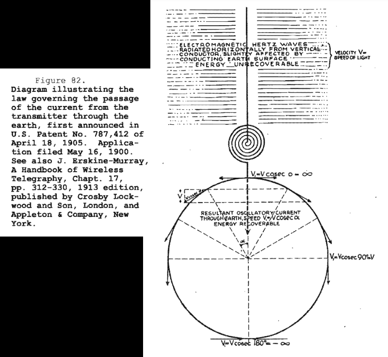
This [Fig. 82] illustrates, on a larger scale, the earth. Here is my transmitter -- mine or anybody's transmitter -- because my system is the system of the day. The only difference is in the way I apply it. They, the radio engineers, want to apply my system one way; I want to apply it in another way.
This is the circuit energizing the antenna. As the vibratory energy flows, two things happen: There is electromagnetic energy radiated and a current passes into the earth. The first goes out in the form of rays, which have definite properties. These rays propagate with the velocity of light, 300,000 kilometers per second. This energy is a exactly like a hot stove. If you will imagine that the cylinder antenna is hot -- and indeed it is heated by the current - it would radiate out energy of exactly the same kind as it does now. If the system is applied in the sense I want to apply it, this energy is absolutely lost, in all cases most of it is lost. While this electromagnetic energy throbs, a current passes into the globe.
Now, there is a vast between these two, the electromagnetic and current energies. That energy which goes out in the form of rays, is, as I have indicated here [on the diagram of Fig. 82], unrecoverable, hopelessly lost. You can operate a little instrument by catching a billionth part of it but, except this, all goes out into space never to return. This other energy, however, of the current in the globe, is stored and completely recoverable. Theoretically it does not take much effort to maintain the earth in electrical vibration. I have, in fact , worked out a plant of 10,000 horsepower which would operate with no bigger loss than 1 percent of the whole power applied; that is, with the exception of the frictional energy that is consumed in the rotation of the engines and the heating of the conductors, I would not lose more than 1 percent. In other words, if I have a 10,000 horsepower plant, it would take only 100 horsepower to keep the earth vibrating so long as there is no energy taken out at any other place.
There is another difference. The electromagnetic energy travels with the speed of light, but see how the current flows. At the first moment, this current propagates exactly like the shadow of the moon at the earth's surface. It starts with infinite velocity from that point, but its speed rapidly diminishes; it flows slower and slower until it reaches the equator, 6,000 miles from the transmitter. At that point, the current flows with the speed of light - that is, 300,000 kilometers per second. But, if you consider the resultant current through the globe along the axis of symmetry of propagation, the resultant current flows continuously with the same velocity of light.
Whether this current passing through the center of the earth to the opposite side is real, or whether it is merely an effect of these surface currents, makes absolutely no difference. To understand the concept, one must imagine that the current from the transmitter flows straight to the opposite point of the globe.
There is where I answer the attacks which have been made on me. For instance, Dr. Pupin has ridiculed the Tesla system. He says,
"The energy goes only in all directions."
It does not. It goes only in one direction. He is deceived by the size and shape of the earth. Looking at the horizon, he imagines how the currents flow in all directions, but if he would only for a moment think that this earth is like a copper wire and the transmitter on the top of the same, he would immediately realize that the current only flows along the axis of the propagation.
[*1] Editorial note: The large German-owned radio station at Sayville, Long Island, was constructed by Telefunken (Geselleschaft fur Drahtlose Telegraphie) a few years prior to WWI for communication with a station at Nauen, near Berlin. Suspected of rendering non-neutral service at the outbreak of hostilities, it was taken over by the U.S. Navy Department in July, 1915. The great Tuckerton, New Jersey, radio station was built by the German Homag Company for a French firm. The German company delayed transferring ownership of the transmitter after the outbreak of hostilities, and it too was taken over by the U.S. Navy Department. Tesla was a technical consultant for the Tuckerton station, and received a monthly royalty and consulting fee, until it was taken over by the U.S. Navy Department.
[*2] Editorial note: Reference is to John V.L. Hogan, at that time chief research engineer, National Electric Signaling Company, who was one of the driving forces in the forming of the Institute of Radio Engineers, later becoming its president in 1920. The "they" refers to the work of the General Electric Company's Steinmetz, Berg, Green, and Alexanderson, in collaboration with Fessenden of the National Electric Signaling Company leading to the production of successful alternators operating up to 60 kHz at 100 kW.
[*3] Editorial note: Tesla refers to an adjustable primary inductance rather than an adjustable secondary inductance as shown.
[*4] Editorial note: Capacitance values expressed in centimeters are in electrostatic units; to convert from centimeters to picofarads, multiply by 10/9. Thus, in the situation described, with an antenna of 0.0011 microfarad, Tesla could read an increment of 0.55 picofarad.
The Inventions, Researches, and Writings of Nikola Tesla
The Martin Book
Tesla's Cymatic Research
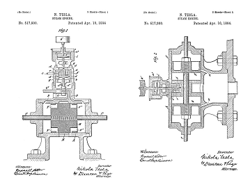
Steam Powered Isochronous Acoustic Oscillators & Generators
Tesla's Electrical Isochronous Oscillators
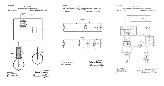
Capacitive Discharge Power Processing
Tesla's Electric Circuit Controllers
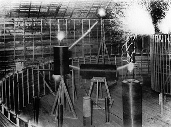
Precision Switching Technology
Tesla Transmitters
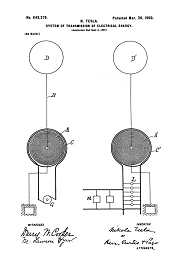
Wireless Transmission of Electrical Energy
Nikola Tesla Receiver Technology
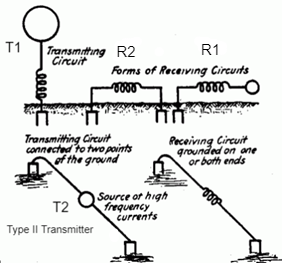
Home Appliances and Industrial Solutions
To the Archive Page Discussion on Tesla's Technology