Tesla Coil Spark Gap
RQ/TCBOR CYLINDER STATIC GAP
Updated Mirror of: https://www.nic.funet.fi/pub/sci/electrical/tesla/misc/sparkgap.zip
This cylinder static gap was designed to quench 6-8 kv running up to 1 kva in more or less continuous duty. It will quench 6-8 kv up to 2.5 kva intermittent, depending of course on your run times, three minutes being quite tolerable. These gaps are very functional and can be easily moved from coil to coil. Complex gap systems can be built up using more than one unit. These systems can provide excellent power handling flexibility and efficiencies. Two gap units may be hooked in series for quenching up to 1.2 kva continuous, or 3 kva intermittent.
hese gaps can also be employed with great effectiveness when used with a rotary gap. Units may be run in series with a rotary gap. Excellent quench times can be achieved at very low cost on medium powered Tesla coils in this fashion.
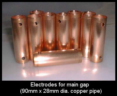
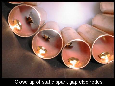
The copper pipe electrodes offer a large surface area to assist in quenching. The electrodes are cooled by an air stream which also removes hot ions from the gap during operation. The air stream is provided by a 5-1/4" muffin fan mounted on top of the gap unit. The gap is remarkably quiet, and the arc is shielded by the PVC pipe eliminating the UV hazard.
Construction of a gap unit requires the following parts:
A five inch length of 6" PVC drain pipe
15" length of 1-1/2 inch hard copper water pipe
One end cap for the 6" PVC drain pipe
One 5-1/4 inch, high CFM, muffin fan
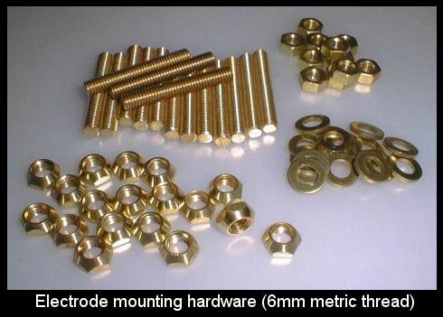
14 1/4" Brass machine screws with nuts and washers
4 #6 Brass machine screws with nuts
3 feet of good quality lamp cord
18" of thick wall vinyl tubing
Stiff epoxy
Cut the copper water pipe into seven two inch sections and polish the pieces. Drill two holes in a line 1" apart and 1/2" from the top and bottom of each section.
Drill two corresponding holes, larger than those drilled in the copper pipe, into the PVC drain pipe. The holes in the copper pipe should be snug for a 1/4" machine screw. The holes in the PVC pipe must be loose, allowing play to properly gap the electrodes. Do not drill all of the required holes into the PVC pipe at once, work with one electrode at a time.
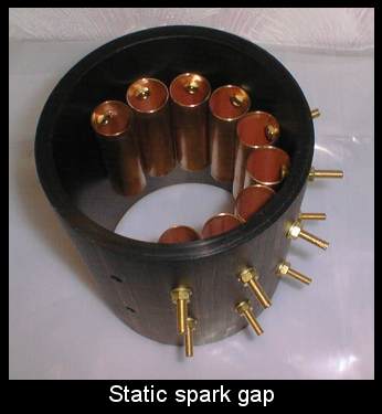
Mount the first electrode. Two 1/4" brass machine screws are used with the screw heads inside of the copper pipe and the threaded ends extending outside. Install a washer and nut on the screws and tighten until snug but DO NOT OVER TIGHTEN. Measure out ~2-1/2 inches and drill two holes for the second electrode. After fitting you may find it necessary to file out the holes before you can get a parallel gap. Use a feeler gauge and adjust until you can set a gap of .028 inches with the nuts snug. It is important that the gap be equal and parallel up and down the entire 2" length of the copper electrodes.
When the gap can be set, remove the first two electrodes and smear a stiff epoxy on the back sides around the screws. Reinstall the electrodes and snug the washers and nuts down, adjusting as necessary for a parallel gap. It is important that the epoxy gushes out around the nut and washer. As the gap is run over time, heating and cooling will loosen the mounting nuts unless there is sufficient epoxy on the threads to permanently affix them. Make sure to wipe away the excess and thoroughly clean the screw threads above the nut. The screws serve as the terminal posts and if the threads are fouled with epoxy you will have to fight to get your connections on and off.
Proceed with drilling the next two holes and fit the next electrode. Gap as above. When you can achieve a perfect gap, remove the electrode and bed it with epoxy. Check your gaps carefully and frequently, once the epoxy sets you will never have to worry about them again!
After all seven electrodes are installed, place the gap unit under a heat lamp to speed the epoxy cure. Then assemble the blower unit.
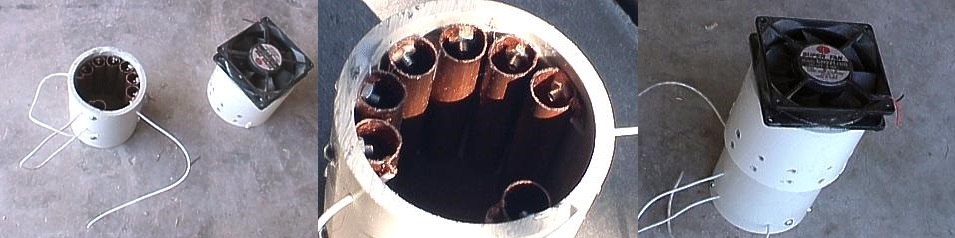
Center the muffin fan on the PVC end cap and scribe a circle for the fan cutout. Cut the circle out and drill four holes for the muffin fan mounts. Mount the fan with the four #6 machine screws and nuts so the air flows from the bottom of the gap unit up.
Slide the lamp cord through the vinyl tubing and solder the ends of the wire to the muffin fan terminals. The vinyl tubing is important to provide some protection from the high voltage present on the exposed gap terminals, but do not rely on it. Route your 110 volt line away from all high voltage points with nylon wire ties and provide for line filtering when using the gap.
When the epoxy has set, mount the fan assembly on top, but do not glue it into place. The top is removable for easy cleaning between the electrodes with #600 or higher sandpaper wrapped on a shaved down tongue depressor. I build a wooden or plastic tripod base to set the gap unit on. The gap base should allow at least 3" of space below the gap unit for airflow, I allow 4 inches.
The gap as sketched shows the installation of an arc shield between the two end electrodes. This is important despite the fact that the gap here is quite large. With a piece of 3/8 inch plexiglass glued in this spot, gap units can be run together in series to quench higher voltage power supplies without the arc taking the shortcuts.
When run with neons at 12 kv rms, two gap units are used and all the electrodes are run in series. If higher voltage is used (up to 25 kv) gap units may be added in straight series connection providing your kva load does not exceed the individual gap unit rating for long run times. Allow 1000 volts per gap between electrodes (.028").
Quenching performance can be increased by mounting an air choke on the gap base. This will act to prevent air from passing up the center of the gap where it takes up little heat and fewer ions. I use a piece of 3" or smaller PVC pipe set on the gap base and passing up into the bottom of the gap just under the electrode ring. This forces the air to pass through the electrodes and between the gaps to remove heat and ions and improves the run time. Performance may also be improved by fitting finned, cylindrical heat sinks, available at the electronics surplus or many hamfests, into the center of the copper electrodes. A little heat sink paste here is helpful to assist in heat removal from the electrode and preventing corrosion from the aluminum/copper contact. Oxides formed by contact corrosion are poor heat conductors. For maximum effectiveness the heat sinks should be cleaned of any coating at the contact points. Finned heat sinks installed in this fashion will dramatically increase the surface area of the electrodes. This is especially true in gaps of this design using larger copper pipe and bigger gap rings.
When running these gap units as part of a system with a rotary, all gap adjustments are still made on the stationary electrodes of the rotary gap. Insert one .028" static gap (distance between each electrode in this unit) in series for every 2000 volts of line input to the coil, then set the rotary gap adjustment so that the coil system fires smoothly and reliably. Suppose your rotary system has a 12 kv line input: every electrode on the cylinder static gap unit is gapped at .028", and you need a total of 6 of these static gaps in series with the rotary for the system to function properly at 12000 volts. Two cylinder static gaps run in series with the rotary will provide excellent quenching up to 2 kva continuous, 3.6 kva intermittent. Your rotary will require a much smaller gap, and your quench time will have dropped considerably. Your rotary will run cooler, your run times will be longer, and your secondary spark will be better.
Another benefit of gap systems with a rotary is that the wear caused by the hot arc is distributed among many gaps with a large surface area. The arc at the rotary is both cooler and shorter in duration, taking stress off of the stationary electrodes and reducing wear at these critical points.
Gaps of this design using 1" diameter copper pipe can be constructed as above to get 12 gaps into a cylinder ring of 13 electrodes. The 1" diameter pipe sections do not sink as much heat, but if gapped at .028 -.030 inches a single unit will quench up to 15 kv rms from neon sign transformers banked up to 1.5 kva intermittent. If the unit is constructed from 1" dia. pipe and the electrodes are gapped at .056 -.06 the arc can be split down two parallel paths (center electrode tapped) for a good quench time with a neon power supply of 12 kv rms in the 1.5 kva power range, this is of course intermittent operation but will use only one gap unit. Using the flaired end of 6" pvc drain pipe will give enough room to squeeze in all of the required electrodes and the arc shield, but the result is the fan must be custom mounted, and may have to be glued into place.
https://hotstreamer.deanostoybox.com/stk/tc/rqgap.htm
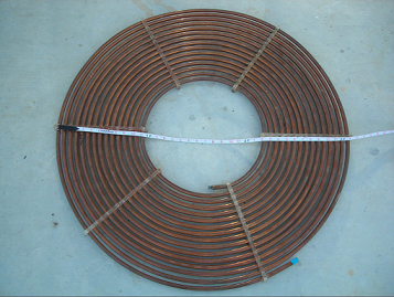
'The famous cylinder static gap'
Images from https://deepfriedneon.com/tesla_staticgap.html above,
And https://www.sky-chaser.com/tcpart1.htm, below.
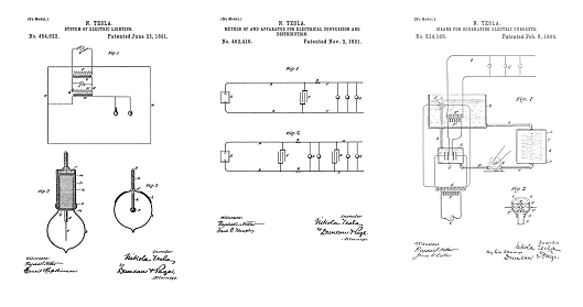
Tesla disclosed magnetically quenched spark gaps in Fig 133 of the following lecture:
EXPERIMENTS WITH ALTERNATE CURRENTS OF HIGH POTENTIAL AND HIGH FREQUENCY
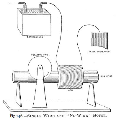
Lecture by Nikola Tesla Presented to the Institution of Electrical Engineers, London, February 1892
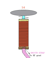
High Performance Tesla Resonator Design
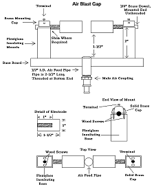
High Performance Air-Blast Spark Gap
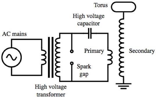
Tesla introduced his resonating coil technology in lecture in 1891
Tesla's Electric Circuit Controllers
Precision Switching Technology
Tesla's Electrical Isochronous Oscillators