The Story Of Dr. Nikola Tesla
The Lab-Tesla Commentary Focusing on Nikola Tesla's Patented Technology, Lectures, and Wireless Development
For people who are interested in Tesla, the man, his origins and background, Lab-Tesla hosts a short biography.
The Arc-Light Men
https://en.wikipedia.org/wiki/Arc_lamp
When Tesla began his career as a private inventor, researcher, and developer of technology, electricity was just beginning to become widely used in arc-lighting systems. Arc-light systems were the first electrical theater lighting to successfully replace "lime light". The term "lime light" persists, but this technology is long dead: Sticks of quicklime, calcium oxide, were heated in an oxyhydrogen flame. Just before the material begins to melt, and as it is melting, it produces a brilliant white light that was used for indoor stage, and outdoor lighting for fairs, theatrical events, and other "spectaculars." The high temperatures involved would quickly raise the air temperature in a closed indoor environment like a theater, and molten quicklime is an extreme fire hazard, especially on wood plank flooring. The process can also disperse smoke-like particulates that dry the throat, and irritate the eyes.
The first electric arc-light systems were direct current, or DC powered. The Arc-Light Men connected DC generators to two sticks of carbon. They touched the carbons together momentarily to establish an arc of electric current between them, and then separated the carbons a bit to maintain the arc without overloading (shorting out) the power supply. This produces a brilliant, but un-naturally harsh, blue-white light. Arc-lights are still used for demonstrations of legacy, high-powered, search lights.
It should be noted here early in the overall presentation that electric arcs have a pretty high electrical resistance. The longer the arc, the higher the resistance is, and this includes multiple arcs in series as was common in large arc lamp systems. This resistance results in the heat and light production by the arc, and the amount of power that is consumed by passing an electric current in the form of an arc through the air can be excessive. Not only are heat and light produced by the arc, but they burn nitrogen in the atmosphere creating nitrogen oxides, and they produce ozone, and these chemical changes consume energy. Also: arcs powered with alternating current produce sound, and energy is also lost here. Whining, buzzing and howling noises from the arc prevented alternating current from being applied for arc-lighting in theaters for instance.
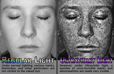
Direct current arc-lighting was considered a signifcant improvement over lime light when it was introduced to the theater. Not because the light was better quality: lime light was considered to be a fair substitute for natural sunlight and actors in particular, loved it: whereas arc-lighting is rich in violets and ultra-violets, it does not have the color balance of more natural appearing light; and actors in particular hated it because it highlights skin and makeup flaws. Actors longed for the pre-arc-light days of "limelight". But arc-lighting, even with the problems it had, greatly reduced the side effects and fire hazard caused by melting calcium oxide in a closed, packed, theater.
In his later lectures Tesla actually demonstrates single terminal vacuum bulbs that produce the lime light effect, and the warm, more natural, color balance: without the excessive heat, open flame, and white hot molten dross involved with lime lights. So it is important to understand this background in relation to the later lecture material on light production for instance. Tesla was also interested in producing high-quality reading lamps.
Tesla's patent record begins on March 30, 1885; when he filed for protection on a new automatic arc-lamp. The patents that quickly followed document that Tesla first developed an entire DC arc-lamp system: DC generator head or "dynamo" complete with current regulators, lamps, and commutator. The system and improvements are detailed in the following section:
Tesla's Arc-Light Technology
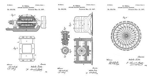
Automatic Lamps, Commutators, Regulators, DC Generator or "Dynamo"
396,121
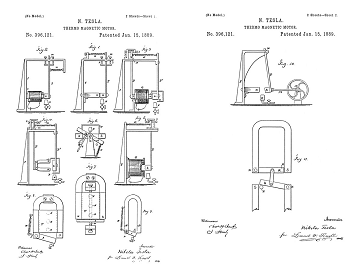
On March 30, 1886, Tesla filed for patent protection on a Thermo-Magnetic Motor. US Patent 396,121. --- This is not a free-electricity generator, nor is it some type of perpetual motion motor... In this patent Tesla shows little gas jets as the proposed heat source, but in the actual application the heat source is the arc, from a commerical type carbon arc-lamp. The purpose of these patented motors is to drive clockwork which advances the carbon electrodes automatically in commerical arc-lamp systems, so you do not need an attendant present at the lamp constantly turning the adjustment screw as the carbons are consumed by the arc during a performance, or during the work day on a factory floor. These little thermo-magnetic motors do not produce much force at all, but they are perfectly suitable for advancing the carbons in an arc-lamp. Arc-lamp automation was the intended application for this technology, but in modern industrial society these motors may find applications in process control systems.
There is no record that Tesla ever constructed his Pyromagneto-Electric Generator. This application was filed May 26, 1887 and did not get approved by the US Patent Office until May, 1890. It comes at a time when Tesla was working with arc-lamp systems and motors, but this is not an arc-lamp or motor patent. It is a type of generator, and is most closely related to the thermo-magnetic motors introduced above. This may be a case where Tesla came upon a simple, workable, idea and decided to apply for a patent without a serious application in mind... Later, he would not be so frivolous in going to the patent office.
Alternating Currents and the
Rotating Magnetic Field
381,968
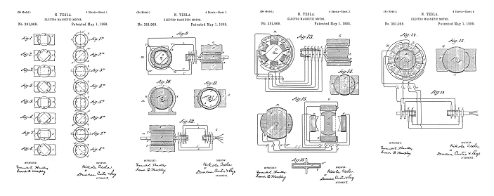
On October 12, 1887, Tesla changed the world with the filing of the application that became US Patent 381,968 - Electro-Magnetic Motor
https://www.invent.org/inductees/nikola-tesla
Nikola Tesla Patented Induction Motors Are a Class of Particle Accelerators
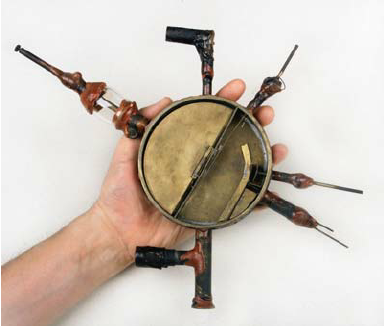
Cyclotron 4-1/2" (11.43 cm) Shown with the top vacuum seal plate and one Dee magnet removed. This is confirmed to be one of the units that were hand-built by E.O. Lawrence from the same piece of brass stock. Click image for higher resolution.
Photo credit: Linda Hall Library
A Tesla induction motor can be examined from the perspective that it operates as, or has the function of, a particle accelerator. Now when most people think of a particle accelerator, they think of something like CERN, that big underground ring with supercooled magnets, and really tiny particles, like hadrons. Well this first Tesla lecture coming up is a description of the first inductively coupled particle accelerator technology. A Tesla generator is an electron accelerator. The accelerated electrons are then used to accelerate a particle. The particle here is a substantial mass of iron that forms an armature, so it's a pretty big particle, and because of its mass, it has practical applications as a motor. But really what Tesla has done is, he has designed a rotational particle accelerator technology and his research, from the very beginning, dives deeply into high-energy particle physics: his particles are very big, and he does not accelerate them to near light speeds, and we can still call them motor armatures; but in fact Tesla patented motor geometry produces working models of how similar particles work on a very small scale, and on a very large scale, and actually provide insight into how tiny particles like nuclei are shaped and function in nature, and how large macro particles, like neutron stars and black holes, are shaping fields and functioning magnetically.
So when you are looking at Tesla patented electromagnetic geometry, it does not stop there with just the motor, generator, regulator, or transformer... Nature is using all of the principals that Tesla discovered in order to shape the environment that we live in. And if you do not understand Tesla, your understanding of our universe is critically incomplete. Tesla was teaching fundamental Unified Field Geometry. What he was teaching, is true. His motor not only turns, it's a research platform into high-energy rotational particle physics and wireless energy transmission, and the truth about his technology was first buried with deliberation, and then heaped over with ignorance.
Thomas Commerford Martin worked hard to document a solid foundation of Tesla's applied technology, but it must be understood early that just because Tesla patented a device, say a generator, in an application, say for arc-lighting, does not mean that is everything there is to know about that generator, or that arc-lighting was all that Tesla used it for.
By this point historically, Martin understood Tesla was making history and Martin made a serious and dedicated effort to assemble as much material covering these early years as Tesla was willing to put into print.
The Inventions, Researches, and Writings of Nikola Tesla is now a public domain historical document and the entire book with diagrams has been transcribed into pages and linked into the site here. Critical historical documentation is now online in html for the first time due this effort. But even with the most complete text and the highest resolution images, Tesla is a difficult study; he was proud of his linguistic skills, English was not his native tongue. As he is speaking he is at the forefront of ground-breaking, world-changing, technological development, and he has seen and understood many things in the laboratory that simply defy description: First because the words did not exist in English to describe the physics Tesla was first to discover, second some of the things he is seeing are simply incredible to the point that words do not adequately convey an understanding of the process being described or examined, third because there were no math tools that accurately described what the eyes were seeing.
For example, Tesla's alternating current motors are universal, everybody reading practically, sees one, and/or uses one, every day, if not multiple times every day. The alternator in your car is Tesla patented geometry. Nobody at all stops to think, or really understand, how an induction motor works; it works and that is about all that is generally understood about this technology. But the beginning of the true story of Tesla's motors and generators is the point where you are standing on firm earth, looking at a peculiar, swirling, sinkhole.... And if you climb or fall in, it is Wonderland, everything is different there... And what makes it truly mind boggling is that Wonderland is the true reality. Our minds are tethered... And there is a language barrier between us, and the truth about these motors and generators. Tesla is both hard to understand, and hard to believe at the same time, but he is always truthful to the best of his knowledge. Tesla knew far more about the technology that he personally researched and patented than anybody in his lifetime, or to present day. He is the ultimate authority until you can prove him wrong in the laboratory using the same equipment that he designed, operated, and patented. The true story of his technology is carefully laid out, he made sure there was a historical record for a guy like me to recover and that there was enough disclosure so that a serious investigator who examined the historical record could completely duplicate all the generator, motor, resonator technology and match their experimental results with what Tesla had observed and recorded. There is a step-by-step learning process, hands-on, where once the equipment is operating both you and Tesla are seeing exactly the same things and then the language barrier drops away... If you believe your own eyes.
The question ends up being a personal one: whether you believe your own eyes, or what you learned someplace else, like in school for example, or what your math equation told you... And more often than not, people will actually disbelieve their own eyes rather than give up a cherished belief or understanding that is glowingly in error. The temptation to do this is great, I have been subjected to this more than once, and there is often peer pressure... Someone telling you, you can't believe these things... "Everybody knows..."
And frankly, quite honestly, what everybody knows is wrong. I can prove it. Tesla himself proved it. Along with the proof, comes a deeper understanding of nature, and it starts by looking at what you already are familiar with, just a little bit differently.
Now the paper. Come back using the link at the end of the section.
A NEW SYSTEM OF ALTERNATE CURRENT MOTORS AND TRANSFORMERS
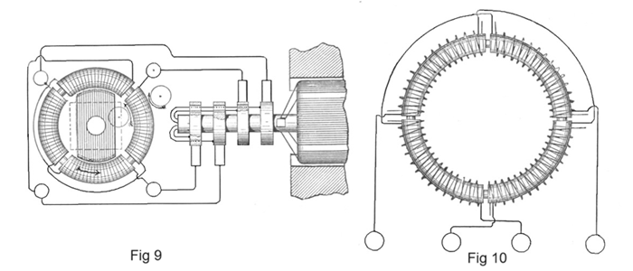
Paper by Nikola Tesla read to the American Institute of Electrical Engineers on May 16, 1888
Polyphase
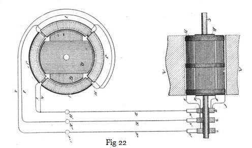
Modifications and Expansions of the Tesla Polyphase Systems
Martin covers the development of the "modern" three-wire polyphase system, where two wires are connected as a common return, and polyphase transformation, again using Tesla's Egg geometry. The patents detailed are 390,413 and 382,282.
A group of Wall St. investors with names similar to Morgan, Carnegie, Rothschild, and Astor stopped the development of industrial power transmission once they gained control of the first batch of low-frequency, heavy iron core, Tesla alternating current, rotating magnetic field patents. They financed the construction of the Niagara Falls hydroelectric plant and they estimated it would take 50 years to recover their capital investment. But even before the low-frequency patents were filed, Tesla was hinting, then later talking seriously, saying that the system he himself had described, and was still working to advance, was becoming obsolete in a sense. In the end, Tesla saw real advantages to using "low frequencies" and iron cores for the industrial generation of power, and the application of that power to turn industrial motors; but by that point a "low frequency" to him was 3000-5000 Hertz, or cycles per second, and our power grid globally is 50-60 cycles.
Tesla's Initial Development of Wireless
If you are here, it is assumed you have covered the preceding material and you are familiar with the basic technology that Tesla introduced in 1888: The Rotating Magnetic Field; and how the majority of this technology was based on a single electromagnetic geometry, demonstrated publicly in 1893 as "Tesla's Egg of Columbus", and you are also aware that Tesla pushed the two-phase generator power supply for the "Egg" to its physical limits in driving the device to produce a field that rotated motor armatures wirelessly at a considerable distance from the transmitter, and at great speed. It would also be accurate to say that Tesla invented, operated, and demonstrated a new class of particle accelerators, and that the field generator of this system was able to couple to, and accelerate, particles, from some distance away. This was advanced research that Tesla had performed on the electromagnetic geometry known as "Tesla's Egg of Columbus" many years prior to public demonstrations of it, and Tesla had determined that the "Egg", while suitable for impressive demonstrations of particle acceleration and wireless energy transmission locally, had an insufficient range, and an insufficent mode of coupling energy to the receiver (it was inductive coupling only), and as such, it was not suitable for a patent as a transmitter of wireless power... But he did patent it for everything else: motor field, - a generator field, - and a transformer, and we can document it was his first research tool into wireless. He was willing to demonstrate it as a wireless transmitter because he knew it would never be a commerical success as such in the hands of any competetor... Because he had already developed better technology that was never disclosed or publicly demonstrated in connection with wireless energy transmission.
There are two points about Tesla's wireless energy transmission technology that remain generally unrecognized, and this results in a misunderstanding about Tesla's development of wireless. The first point is that all of Tesla's single-wire and wireless power transmitters contain iron magnetically coupled somewhere in the transmitter circuit. We have a long way to go here before we introduce what is generally acknowledged as a Tesla wireless energy transmission patent, but even those more advanced, higher frequency, transmitter geometries had iron directly coupled into the circuit somewhere, and the frequencies were kept very, very low by modern radio transmission standards. The second point of importance is the wave form. With a single wire connection you can transmit torque to a motor armature with a pulsed wave or a pure sine wave, but when you transmit energy, power, wirelessly over any distance you really have to have a continuous wave signal to drive the output transmitter or field generator; and if you want communications capabilities you need sine waves, and the ability to modulate them, for effective morse code and voice transmission. Power transmission frequencies can be modulated but the bandwidth is very, very low, and modulating the fundamental frequency of the transmitter would potentially interfere with receiving devices like clocks running at the fundamental transmitter frequency. Further to note: Tesla's single wire and wireless motors operate on power supplies producing output current in the audio frequency range, typically well below 10,000 Hertz, in order to couple in, and deliver torque efficiently, to the iron motor armatures. These armatures get thin and light weight as Tesla reduced the amount of iron in order to reduce the heating and hysteresis losses: high-frequency motors are generally based on thin steel discs, or drums constructed of thin sheet steel, overwound with closed coils. The thin steel is able to reverse magnetic polarities at a much higher frequency than a thick soft-iron construction.
Tesla's advanced wireless technology, at higher frequencies, is all based on fundamental alternating current motor, and power supply, research and development.
455,067
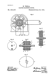
Electro-Magnetic Motor - Jan 27, 1889
We need to stop and look at US Patent 455,067. As the line frequency that is powering a Tesla induction motor is increased, the electrical and magnetic responses in the motor change for the worse. The faster you want the motor to go, the more resistance the power supply sees. The impedance of the armature coils appears to increase with higher frequencies, and they refuse to take power. If you increase the line frequency further, the motor starts to slow down because it is more and more inefficient, and instead of energy being converted into rotation, it goes into heating the iron core.
Tesla knows that reducing the amount of iron in the motor core, and/or adding a capacitor to a motor circuit, lowers the measured inductance of the windings. Inductance is seen by the power supply as an impedance, a resistance to current flow. The bigger the motor coil, or the more iron near it, the greater the impedance that is seen by the generator. At low frequencies these values are not too critical, but if you are trying to run your motors from a power supply operating at say 1000 cycles per second, unless you reduce the amount of impedance seen by the generator, virtually no current will flow through the motor coils, and no power output will be obtained from the motor. So Tesla adds a substantial value of capacitance to the armature windings (and in the field in Patent 464,666). This greatly improves the performance of an existing motor when it is required to operate with a higher frequency power supply. It turns out that at low frequencies, like 50-60 cycles, the value of the capacitor required to completely cancel the impedance of the motor windings is very, very large. But as the frequencies are increased, the capacitance required is reduced to a managable value, and Tesla incorporates this capacitance directly into the iron armature as part of the construction. In the process of doing this he reduces the amount of iron, which reduces weight, which also lowers the internal inductance because there is less iron in close promixity to the copper conductors. This incorporation of capacitance into a particle model is also an important advancement. It improves the efficiency of high-speed, high-energy particle accelerators by changing the electrical function of the particle itself. It also makes for a much more powerful and efficient high-speed motor. We see will see this applied in Tesla transmitter circuits below.
The armatures shown by Martin in Figs 309 and 310, equipped with slip rings, were surely tested as wireless transmitters simply by connecting a high-energy generator and sufficient capacitance across the armature coils while the armature was held in a stationary position: then conductive eggs, discs, etc.. would be used as the test receivers as Tesla advanced his iron-core transmitter geometry. Several other armatures in the same image had hollow shafts: the ends could be uncapped and the wires connected to the armature windings withdrawn. They could then be connected to slip rings or external power supplies; when used inductively the wires were connected together and tucked back into the hollow shaft and covered with a cap. Given his knowledge and documented inventory of equipment he would have been seriously negligent if he had not performed such tests: you can be assured he generated large, powerful, fields using these specific devices in exactly this manner. Tesla also demonstrated a motor with a stationary armature and rotating drum field which was turned smooth for belting directly to appliances: no pulley.
This work was all performed very early in Tesla's development path. Armature driven motors were discussed in Tesla's 1888 paper, paragraph 2, very bottom, which he only mentions "incidentally". If he did not have the test motor already, it was promptly constructed, tested extensively, and later displayed at the 1893 World's Fair - Exhibit M. - Click on the high resolution Image Here. <- The armatures shown with dimples on the ends of the shaft are all hollow shaft armatures. The caps on the ends of the armature shafts have a small hole in them where a stiff wire hook was inserted to pull the caps off. The same stiff wire hook was then used to fish the armature leads out of the hollow shaft. A least 6 of these armature designs on the table were tested as inductive wireless transmitters. Large capacitors were placed in the circuits with the coils in accordance with 455,067 above.
The final Tesla transmitter patent, U.S. Patent 1,119,732, is an armature driven transmitter, and directly relates to this work. These same armatures were also fitted with slip-rings and tested as generator armatures.
By this point, Tesla was surely using large capacitors to cancel some, if not all, of the inductive reactance in each of the four windings of The Egg during wireless demonstrations. This capacitance was likely applied to the circuit out of view, and values were preselected for predetermined frequencies. At low frequencies, 25-30 Hz, a very large capacitance would be required. At 250 Hz the value would be lowered.
It is important to note that when Tesla applies a capacitor to a circuit, whether that circuit is a motor coil, or a transmitter coil, the value of that capacitance is always adjusted until the circuit is electrically and mechanically in tune with the frequency of operation. Tesla's documented skills in tuning electromechanical circuits began way back in 1886-7 with his use of the telephone as an instrument to detect synchronism in motor circuits and cores. Though not publicly disclosed at the time of this patent filing, the development of this motor required advanced instrumentation, and likely independantly powered strobes were employed.
405,858
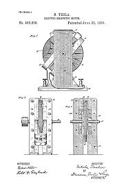
Electro-Magnetic Motor - Jan 8, 1889

405,858 - Photographed at Tesla's World's Fair Exhibit.
US Patent 405,858 is literally the cyclotron of Tesla patented particle accelerator/motor technology. The armature is constructed of a spiral winding of iron wire or ribbon, or concentric rings of iron. As is required with Tesla's technology, the iron in the core is carefully insulated. This construction produces an electromagnetically resonant iron disc armature. This machine is more of a benchtop research particle accelerator/wireless transmitter than it is a motor designed for a commerical application. It shares many electromagnetic congruencies with the cyclotron patented by E.O. Lawrence in 1934: In this Tesla motor, coils D provide the power to induce rotation in the armature, in the cyclotron the frequencies are too high to use coils, so the driving magnets "D" in the cyclotron are made of sheet copper, they are actually shaped liked two letter "D"s, and they induce rotation to the particles traveling along a spiral path inside of them. - Another way to look at this, the cyclotron is a type of Tesla high-frequency motor, where the frequencies are so high, you are accelerating really small particles rather than a larger iron-mass armature.
I want to stop and insert a quick note of interest. These two armature geometries, the insulated spiral disc and the insulated concentric ring are often repeated in Native American petroglyphs and pictographs throughout the American South West.
The armature described in Tesla patent 405,858 is resonant, open-ended, iron-core Tesla transmitter geometry. It is patented and shown as a high-speed disc motor. If I am understanding the electromagnetic functions of the armature presented in this motor patent correctly; the armature disc has no rim speed limit. Iron shaft technology is subjected to rim speed limits that are about 1/3rd of the fly-apart speed. Flywheels and motor armatures are limited to a rim speed of 60 miles per hour commerically, because regardless of the construction; the iron starts to stretch, crack, and fail at rim speeds of about 180 miles per hour, and failures at speed are disasterous. The engineers put in a 3x safety margin on rotating shaft equipment commerically.
But the disc motor shown in 405,858 takes advantage of voltage differences and magnetic attraction between insulated turns of an iron spiral or ring constructed disc armature. The more magnetic energy that is loaded and stored in the armature, the more tightly the armature is attracted to itself, and this resists the pull of the centrifugal force that wants to tear the rim apart. I believe this motor has no real speed limit outside of the problems associated with dynamic balance of the armature and bearing vibration issues.
The motor is shown powered by a single phase circuit with a return wire. But this motor armature can be driven single wire for sure, and very likely serves as a demonstration device for the functions displayed in wireless motor armatures.
This particular patent represents an enormous leap from all the previous Tesla motor patents. Like the cyclotron, the magnetic field core A is divided into two opposing poles which sandwiches the enclosed magnets D, and the armature E. It is the angular displacement of the magnetic lines which induces rotation in the armature, and this design can be driven to extremely high speeds simply by increasing the power and frequency of the supply.
The rim of the armature in this motor is completely open to the environment without any magnetic obstructions outside of the narrow lapping over the rim of the coils D D. The laminated magnetic frame A does not enclose the rim of the armature.
It should also be noted that the resonant electromagnetic function of this armature is due to the fact that the construction incorporates internal capacitance into the iron core geometry. Circuits can be linked together in multiple ways: inductively using magnetically linked coils, capacitively using an insulating dielectric to transfer energy, and conductively, using a wire to deliver a current. Direct, or DC current, can only be coupled conductively, but alternating or pulsating currents can be delivered by any one of these means, or by a combination of them working together. Internal capacitance in an iron core transmitter opens the door to adding capacitive coupling to the receiving motor armature, in addition to purely inductive coupling.
424,036
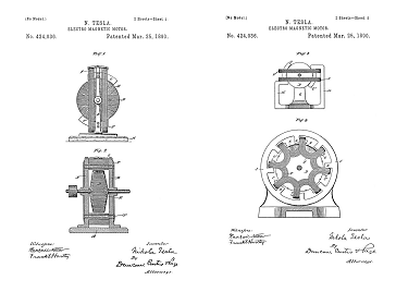
Electro-Magnetic Motor - May 20, 1889
There is as much to say about these motors as there is to say about 405,858 above. At this point in the commentary, if you have been following along closely, you should be able to recognize that the motor technology previously discussed in US Patent 405,858 can be operated with a single-wire as a motor, wirelessly as a motor, or single-wire as an iron-core transmitter. The motor technology disclosed in 424,036 can only be operated as a motor: this is Tesla receiver geometry, not transmitter geometry. As a motor it can be operated with a single-wire and no return, or wirelessly.
406,968
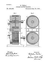
Dynamo-Electric Machine - March 23, 1889
The above is a self-excited DC generator or "dynamo" based on the Faraday uni-polar or Homopolar generator. These Faraday generators use a disc, or a cylinder, mounted to spin in a magnetic field. Tesla adapts the principal into an efficient self-exciting power supply. Closed coils are used to produce the magnetic field in the iron casting, and the rotating parts combine both disc and cylinder (hollow drum) type conductive geometries, mechanically engineered as pulleys. By belting the two pulleys together with a conductive strap, the output was nearly quadrupled, and a practical laboratory power supply and research tool was developed. In order to start the generator, the input power pulleys were belted with leather belts to the lab power supply. The pulleys, and the conductive strap, were turned mechanically with steam power. Once spinning, a starter battery was applied to the contact terminals and a DC current was flashed across them momentarily to energize the field magnets. Once flashed, the field magnets remained self-excited as long as power was taken off the output terminals. If it was used frequently the residual magnetism in the iron core would restart the generator without flashing the contacts.
The technology and principals involved with this patent are significant. This patent formed the basis for an article in Electrical Engineer, Sept 2, 1891. A careful study of this patent reveals that it was the research tool and physical science proof used in the development of the armature geometry patented in 405,858 and later in the Coil for Electromagnets, and in later two-terminal Tesla transmitter geometries. This technology is also discussed in the section on Self-Excitation. It is likely this was also the intended power supply to bias coherers for Tesla receiving stations.
The next sections are presented back-to-back-to-back. Follow the links below to the material, and then jump back with links to the archive at the ends of the sections. Enjoy the ride!!!
Self-Exciting Dynamos and Alternators

Rectification, Energy Conversion
Nikola Tesla Patented Motor Armature Geometry
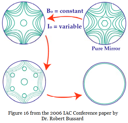
Compression Physics, Polywell Research
THE TESLA EFFECTS WITH HIGH FREQUENCY AND HIGH POTENTIAL CURRENTS
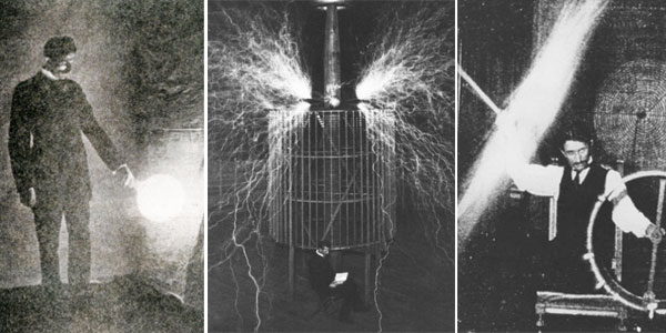
Chapter XXV - The Martin Book
Chapter XXV in the Martin Book is where Martin moves ahead from Tesla's motor technology and polyphase systems, and introduces the "high-frequency" alternators 447,920 and 447,921 through Tesla's lectures. This paper is an introduction to the Tesla Lectures on high-frequency current.
EXPERIMENTS WITH ALTERNATE CURRENTS OF VERY HIGH FREQUENCY AND THEIR APPLICATION TO METHODS OF ARTIFICIAL ILLUMINATION

Lecture by N. Tesla before the American Institute of Electrical Engineers at Columbia College, N.Y., May 20, 1891
First Tesla Two-Terminal Transmitter
By this point we have covered a lot of material. If you are still here, it is assumed you have read the previous two lectures at least once through, and have looked at the source patents, as well as the magazine articles that Tesla references. This is the only place on the Internet where all of this information is both hosted in one place, and correctly linked together. The assembly, and production, of these pages in html represents an enormous effort, and disclosures of privately obtained research results. Please consider supporting Lab-Tesla with a donation, this is a unique resource.
In the previous lecture, Tesla has focused almost exclusively on the production of light effects, which I consider to be important, but which are secondary to the modern Lab-Tesla goals of demonstrating wireless motor technology. But in the lecture just linked, Tesla disclosed power supply information, and patented single-wire technology that have to be mastered, or at least understood, in order to make a wireless motor turn, or to understand how it is done. No return circuits are used in any of the bulb demonstrations up to, and including, Figure 124. One of the first concepts to understand in Tesla's wireless power transmission is that no return circuit is required.

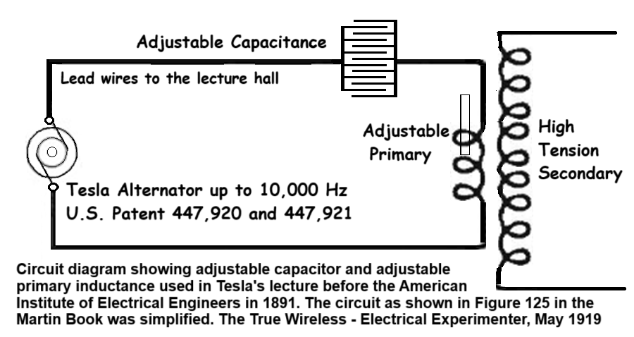
Figure 125 is the classic Tesla iron-core wireless power transmitter circuit. The circuit is powered with a belt driven high-frequency alternator that contains iron in both the core and the field, and the output is an impure sine wave, the wave form is a little jagged, and there is frequency drift expressed. In an amplifier you would say there is harmonic distortion and drift. Tesla got it as clean as is humanly possible with line-shaft power, cleaner than anybody else could have obtained with the same equipment, but you can never get a perfectly clean sine wave from an alternator when your power supply is an engine driving a shaft and pully, turning a flexible belt. Line-shafts flex and twist, and the flexing and twisting shows up as distortion in the output signal. The power supplies were "smoother" than internal combustion engines generally, but variations in speed could be expected from the governors, especially in older equipment. There are also energy pulses when the steam valves open, and these are more pronounced on smaller engines and at higher steam pressures. These all result in a loss of signal quality that prohibits the transmission of messages with this system.
Tesla states that he can reach frequencies as high as 33,333 cycles per second (2 million cycles per minute) using the generator shown in US Patent 447,921, but he states that the demonstration shown in Fig 125 is performed with a generator running at low speed, and specifically identifies the machine, shown in Fig 97, with a steel disc armature rimmed in wrought iron, revolving inside a field magnet of wrought iron containing 384 pole projections. Tesla calls this high-frequency, but all of the experiments and demonstrations are performed using energy in the audio frequency range. Tesla stated in the 1888 paper that he uses a telephone receiver to tune and measure motors, and he places an unconnected phone between the two suspended plates as a receiver/detector during the demonstration of the circuit shown in Fig. 125. A disconnected telephone acts as a wireless receiver when it is properly applied, adding a pickup wire increases the volume, and it screams loud enough to note the attention of an audience if just one wire is touched to one of the plates. Tesla discusses wireless telephony in his deposition on alternating currents.
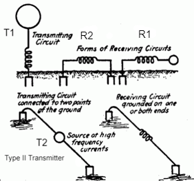
The circuit shown in figure 125 can be modified or applied several different ways. It is demonstrated on a stage with both plates insulated in the air, but it can be operated with one plate in the air and the other plate buried in the ground (T1), or with both plates separated by a considerable distance using insulated wire, and then buried in the ground (T2). This second configuration, two separated plates buried in the ground, is known as the Type II transmitter. Tesla later patented a unique rotational receiver system, typically shown in US Patent 787,412, and others, to receive a low power communications signal using the transmitter circuit shown in Fig 125 as the signal source. These rotational receivers will work in either the R1 or R2 configuration. The receivers have a commutator drum that must be rotated in synchronism with the generator G in Fig 125, or generator B in Fig 1 shown in 787,412. This rotation in the receiver drums can be provided by an independently powered motor that is capable of maintaining a constant speed in relation to the generator speed; wind up clock work; or it can be turned with a steam driven clock shaft using 514,169. When the speed is correctly synchronized and the brushes aligned, the remote generator/transmitter will charge the capacitor in the receiver with enough energy over a few cycles time to activate a relay or flash a light. The charge/discharge timing is commutated on a second rotating drum. This is very low bandwidth, but the technology is not difficult to construct, or expensive to use, and it works for something like Morse code. Like the transmitters, the receiver plates can be configured multiple ways.
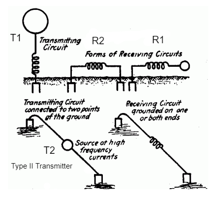
Tesla abandoned the Type II transmitter configuration when he developed more advanced, more powerful, capacitive discharge harmonic oscillators: but the Type II transmitter works fine with 447,920 for communications purposes. Both R1 and R2 receiver types will work fine with either T1 or T2 transmitter configurations, but as the transmitters get more powerful, and more expensive, it makes more sense to focus the effort into the less expensive T1 type. See Tesla Receivers -- Especially Rotational Receivers
BTW, the patent file date on the receiver linked above is way out of order in the development timeline, we do not know when Tesla started working with this rotating drum receiver technology, but the transmitter circuit was disclosed in Fig 125 of the previous lecture. We still have motor technology to complete before we examine wireless receiver technology in depth, and Tesla patented motors as wireless receivers... The point here is that radiation physics and radio engineering, including the supporting mathematics, cannot find a transmission mode that could possibly deliver significant torque to a wireless motor, nor can they find a transmission mode at these frequencies for efficient radiation at all.
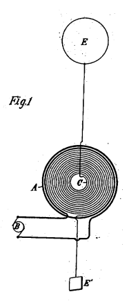
US Patent 787,412 - Fig 1
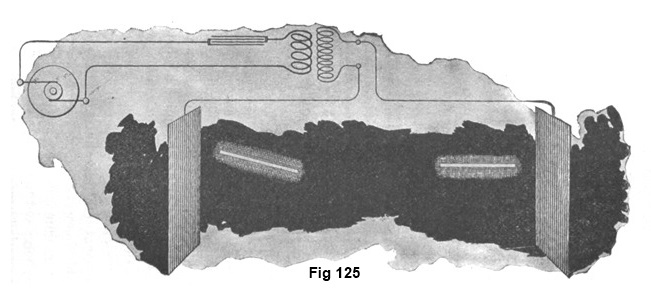
It is important to note that in all of the transmitter patents showing Tesla high-frequency alternators 447,920 -and- 447,921 as the primary power supply, labeled "B" in the patent diagram above [often labeled "G"]: the actual circuit Tesla used always included the capacitor shown in Figure 125, and both the capacitance and the primary inductance were adjustable as shown in the detailed circuit diagram above from The True Wireless. Wireless communications, and even effective lecture demonstrations, using high frequency alternators require frequency stable rotational power supplies to drive the alternator. When Tesla made lecture demonstrations he personally set up the alternator on a suitable steam engine, then he spent time with the engine and alternator to find the "sweet spots", the speeds at which the engine and alternator worked together best, with the most stable output frequency from the alternator. Then he went to the lecture hall leaving an assistant to monitor and control the power supply. Once in the lecture hall he tuned the primary capacitance and the primary inductance to the "sweet spot" frequencies already established during setup and testing in the mechanical room. This would be suitable for lecture hall demonstrations, but in actual wireless communications the application of isochronous generators becomes mandatory, and all circuits must be tuned and concatenated.
BTW, Fig 127 in the previous lecture is the classic spark excited Tesla Coil. Tesla begins researching resonance, - impedance, - and harmonics in spark excited circuits. This becomes important later, we see the beginnings now... But the critical disclosure for us is the transmitter technology diagramed in Fig 125, and the fact that this circuit included adjustable capacitance and inductance, and these values were changed in order to maintain the tune at different alternator speeds.
EXPERIMENTS WITH ALTERNATE CURRENTS OF HIGH POTENTIAL AND HIGH FREQUENCY

A LECTURE BY NIKOLA TESLA PRESENTED TO THE INSTITUTION OF ELECTRICAL ENGINEERS, LONDON, FEBRUARY 1892
The Development of Single Wire Power Delivery
Single-wire technology had been publicly demonstrated in lecture in 1891, but these are industrial patents for high-energy applications like electric railways. The motor shown in 514,972 is the industrial lag motor previously patented in 424,036, Fig 4.
514,167
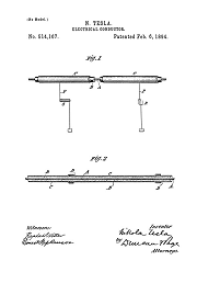
Electrical Conductor - Jan 2, 1892
514,972
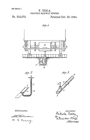
Electric Railway System - Jan 2, 1892
Tesla's Electric Circuit Controllers
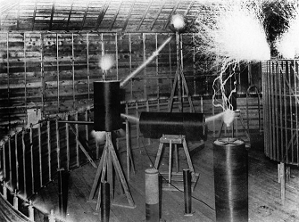
Precision Switching Technology
Tesla's Cymatic Research
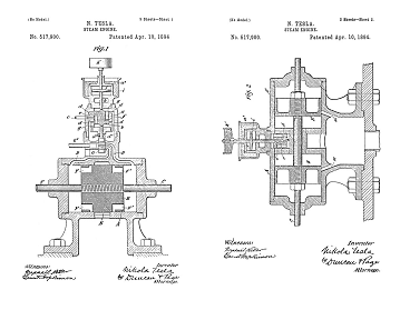
Steam Powered Isochronous Acoustic Oscillators & Generators
Nikola Tesla Receiver Technology
Home Appliances and Industrial Solutions
Tesla's Coherer Technology
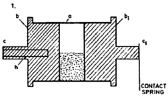
Wireless Communications Receivers
ON LIGHT AND OTHER HIGH FREQUENCY PHENOMENA
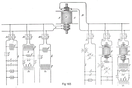
Lecture by Nikola Tesla Delivered before the Franklin Institute, Philadelphia, February 1893, and before the National Electric Light Association, St. Louis, March 1893.
Tesla's Electrical Isochronous Oscillators
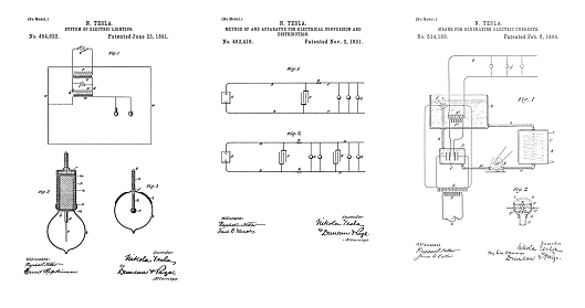
Capacitive Discharge Power Processing
Radiant Light
Both Tesla and Dr Elisha Gray worked extensively with selenium cells, which react to light waves in a way similar to how coherers act when exposed to magnetic waves. Tesla worked with conductive alloy metal plates to act as detectors/collectors of high-frequency radiant light, such as sunlight, and the light produced by carbon arc-lamps, ultraviolet, and even X-ray tubes. I believe based on the background research that these patents were to be used in the first facsimile and image transmission technology. Before he died, Gray was working on primitive closed circuit television and Tesla was very much aware of all of his work.
685,957
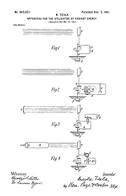
Apparatus for Utilization of Radiant Energy - Mar 21, 1901
685,958
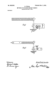
Method of Utilizing Radiant Energy - Mar 21, 1901
NIKOLA TESLA: LECTURE BEFORE THE NEW YORK ACADEMY OF SCIENCES - April 6, 1897 - pdf
Edited by Leland I. Anderson
Tesla Fluid Model

Unified Field Mathematics
MAGNETIC LAG
What is Relativity Exactly?
It is important to understand the timeline here. We have been talking about motor/particle accelerator development, and some armature and field improvements Tesla has patented to both produce more efficient motors, and higher-energy magnetic fields for wireless energy transmission research... What I can document here is that the patents are placed on the motor technology long before Tesla makes any additional disclosures, and the patent record clearly shows a thought and development process way, way ahead of what is generally recognized as any serious Tesla work on wireless, or truly high-energy particle physics... Because this is where, and what, the patent record shows Tesla developing and documenting in 1889, and the proofs are the related patents 405,858 and 424,036. Martin identifies 424,036 as a "Magnetic Lag Motor"; in this patent text, Tesla identifies 405,858 by serial number and file date as the origins of the principal used to develop 434,036. There are deliberate differences in disclosures between the text in the Martin book, and the legal patent record text. That is why the Martin book text is transcribed onto the same pages as the legal text from the patents. Don't think anybody can just read some Tesla, or even all of the Martin book, and figure out what Tesla was doing. You have to read everything with a fine tooth comb. Then understanding begins to dawn like a sunrise.
As Tesla is increasing the power, and the line frequency of the alternating current generator supply to the motor/accelerator, something is wrong. As the frequency of the supply current, and the delivered power, are increased to the motor field, and therefore to the armature inductively... The motor starts to slow down again... This is with all the best fine tuning Tesla can do, capacitance has completely canceled out the impedance to current flow seen by the generator... Tesla can measure the current peaks, there is power going through the motor coils, more power than ever before, at a higher frequency and the motor slows down. This is not supposed to happen. Careful measurements reveal what the problem is: the current flows through the motor coil in one moment, and then some time later, the magnetic field that the current impulse generates is produced. In slow speed motors, the current impulse and the generation of the magnetic pole in the motor happen at exactly at the same time as far as measurements can tell; but at higher frequencies the magnetic field lags behind the current impulse. Not to be dissuaded, Tesla figures the problem out, and patents a type of high-energy industrial motors using the former problem to deliver torque to a new class of motors.
At the time, there was a big debate over what was causing the magnetic field to lag behind the current impulses, and Tesla stated that he measured a slowing down of time:
"I had discovered, however, that rotation is produced by means of a single coil and core; my explanation of the phenomenon, and leading thought in trying the experiment, being that there must be a true time lag in the magnetization of the core."
--Lecture before the IEE, 1892.
Look at -- 424,036 - Where Martin discloses that Tesla discovered magnetic lag and was taking advantage of it early in his motor research, and indeed, the patent record supports that. This was no easy task in 1888-89, and new research equipment had to be developed in order to figure out the problem with magnetic lag, and measure it accurately enough to design efficient, high-speed, high-energy, industrial lag motors.
The following sections were all introduced previously through links in the subsection text:
Tesla Transmitters
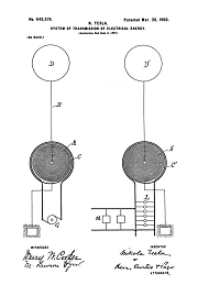
Wireless Transmission of Electrical Energy
ROTATIONAL RECEPTION OF ISOCHRONOUS WAVES
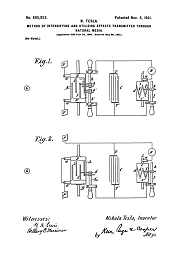
Angular Displacement Receivers
Tesla's Electric Circuit Controllers

Precision Switching Technology
Tesla's Fluid Dynamics
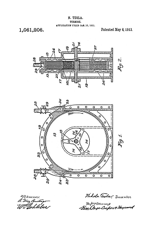
Turbine, Valvular Conduit, Pump, Fountain, Velocity Meters, Aerial Transportation
Tesla's Laboratory Power

Boiler, Steam Engine, Line-Shaft, Belts & Pulleys
Tesla's Lectures

All lectures are formatted with legible images of the original wood cut block prints
Tesla's Complete Patents
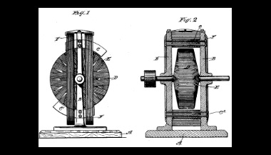
There are 111 unique Tesla Patents
Tesla Articles
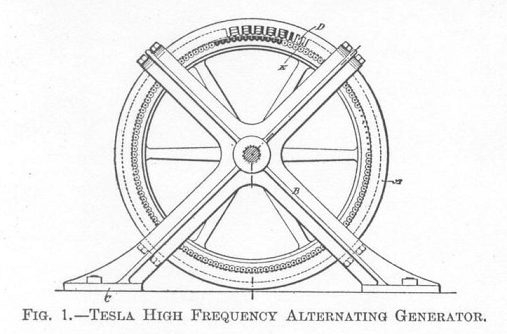
Tesla's Public Disclosures of Means, Methods, Systems, and Apparatus
Ark
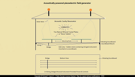
Acoustic Piezo-Electric Field Generator
Note: People keep asking for/about Tesla's Death Ray. Lab-Tesla has to ask for donations to upgrade the lab power supply just to test desktop wireless motors. But... We do understand the technology. So here you go:
TESLA'S DEATH RAY

Tesla's Unpatented Defensive Particle Beam Weapon (The Death Ray)
TESLA'S DEATH RAY

