Modifications and Expansions of the Tesla Polyphase Systems
Chapter IV - The Martin Book
The Martin book contains valuable commentary and diagrams placed in between lectures and patent documentation prepared by Tesla directly. This material makes it easier to follow the evolution of Tesla's development from a four-wire, two-phase, system into the currently applied three-wire polyphase system. Reducing the number of wires required to create the rotating magnetic field while at the same time increasing the shaft power output from his motors was a clear goal for Tesla:
Thomas Commerford Martin
In his earlier papers and patents relative to polyphase currents, Mr. Tesla devoted himself chiefly to an enunciation of the broad lines and ideas lying at the basis of this new work; but he supplemented this immediately by a series of other striking inventions which may be regarded as modifications and expansions of certain features of the Tesla systems. These we shall now proceed to deal with.
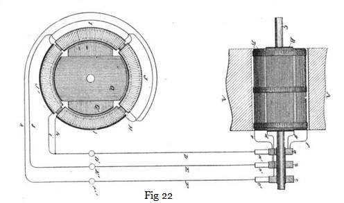
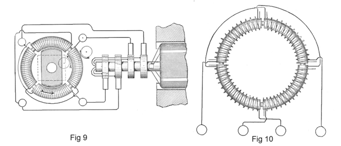
In the preceding chapters we have thus shown and described the Tesla electrical systems for the transmission of power and the conversion and distribution of electrical energy, in which the motors and the transformers contain two or more coils or sets of coils, which were connected up in independent circuits with corresponding coils of an alternating current generator, the operation of the system being brought about by the co-operation of the alternating currents in the independent circuits in progressively moving or shifting the poles or points of maximum magnetic effect of the motors or converters. In these systems two independent conductors are employed for each of the independent circuits connecting the generator with the devices for converting the transmitted currents into mechanical energy or into electric currents of another character. This, however, is not always necessary. The two or more circuits may have a single return path or wire in common, with a loss, if any, which is so extremely slight that it may be disregarded entirely. For the sake of illustration, if the generator have two independent coils and the motor two coils or two sets of coils in corresponding relations to its operative elements one terminal of each generator coil is connected to the corresponding terminals of the motor coils through two independent conductors, while the opposite terminals of the respective coils are both connected to one return wire. The following description deals with the modification. Fig. 22 is a diagrammatic illustration of a generator and single motor constructed and electrically connected in accordance with the invention. Fig. 23 is a diagram of the system as it is used in operating motors or converters, or both, in parallel, while Fig. 24 illustrates diagrammatically the manner of operating two or more motors or converters, or both, in series. Referring to Fig. 22, A A designate the poles of the field magnets of an alternating-current generator, the armature of which, being in this case cylindrical in form and mounted on a shaft, C, is wound longitudinally with coils B B'. The shaft C carries three insulated contact-rings, a b c, to two of which, as b c, one terminal of each coil, as e d, is connected. The remaining terminals, f g, are both connected to the third ring, a.
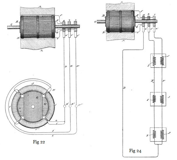
A motor in this case is shown as composed of a ring, H, wound with four coils, I I J J, electrically connected, so as to co-operate in pairs, with a tendency to fix the poles of the ring at four points ninety degrees apart. Within the magnetic ring H is a disc or cylindrical core wound with two coils, G G', which may be connected to form two closed circuits. The terminals j k of the two sets or pairs of coils are connected, respectively, to the binding-posts E' F', and the other terminals, h i, are connected to a single binding-post, D'. To operate the motor, three line-wires are used to connect the terminals of the generator with those of the motor.
So far as the apparent action or mode of operation of this arrangement is concerned, the single wire D, which is, so to speak, a common return-wire for both circuits, may be regarded as two independent wires. In the illustration, with the order of connection shown, coil B' of the generator is producing its maximum current and coil B its minimum; hence the current which passes through wire e, ring b, brush b', line-wire E, terminal E', wire j, coils I I, wire or terminal D', line-wire D, brush a', ring a, and wire f, fixes the polar line of the motor midway between the two coils I I; but as the coil B' moves from the position indicated it generates less current, while coil B, moving into the field, generates more. The current from coil B passes through the devices and wires designated by the letters d, c, c' F, F' k, J J, i, D', D, a', a, and g, and the position of the poles of the motor will be due to the resultant effect of the currents in the two sets of coils—that is, it will be advanced in proportion to the advance or forward movement of the armature coils. The movement of the generator-armature through one-quarter of a revolution will obviously bring coil B' into its neutral position and coil B into its position of maximum effect, and this shifts the poles ninety degrees, as they are fixed solely by coils B. This action is repeated for each quarter of a complete revolution.
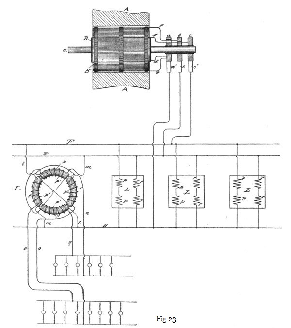
When more than one motor or other device is employed, they may be run either in parallel or series. In Fig. 23 the former arrangement is shown. The electrical device is shown as a converter, L, of which the two sets of primary coils p r are connected, respectively, to the mains F E, which are electrically connected with the two coils of the generator. The cross-circuit wires l m, making these connections, are then connected to the common return-wire D. The secondary coils p' p'' are in circuits n o, including, for example, incandescent lamps. Only one converter is shown entire in this figure, the others being illustrated diagrammatically.
When motors or converters are to be run in series, the two wires E F are led from the generator to the coils of the first motor or converter, then continued on to the next, and so on through the whole series, and are then joined to the single wire D, which completes both circuits through the generator. This is shown in Fig. 24, in which J I represent the two coils or sets of coils of the motors.
There are, of course, other conditions under which the same idea may be carried out. For example, in case the motor and generator each has three independent circuits, one terminal of each circuit is connected to a line-wire, and the other three terminals to a common return-conductor. This arrangement will secure similar results to those attained with a generator and motor having but two independent circuits, as above described.
When applied to such machines and motors as have three or more induced circuits with a common electrical joint, the three or more terminals of the generator would be simply connected to those of the motor. Mr. Tesla states, however, that the results obtained in this manner show a lower efficiency than do the forms dwelt upon more fully above.
Previous Chapter --- Contents --- Next Chapter
Related Patents
The following two patents contain the text from Chapters IV and XXII in the Martin book:
390,413 - Modifications and Expansions of the Tesla Polyphase Systems
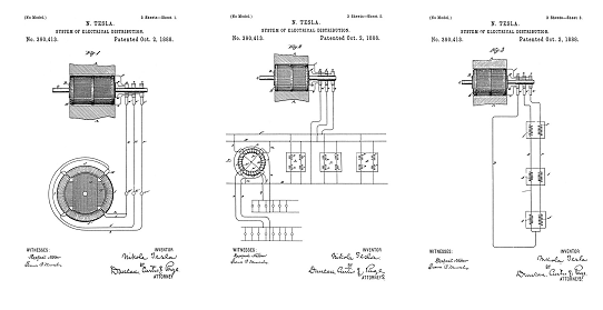
System of Electrical Distribution - Dec 23, 1887
382,282 - Polyphase Transformer
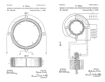
Method of Converting and Distributing Electrical Currents - Dec 23, 1887
To the Archive Page Discussion on Tesla's Technology
Lab-Tesla disclosures on the technology just presented
A NEW SYSTEM OF ALTERNATE CURRENT MOTORS AND TRANSFORMERS
Paper by Nikola Tesla read to the American Institute of Electrical Engineers on May 16, 1888
EXPERIMENTS WITH ALTERNATE CURRENTS OF VERY HIGH FREQUENCY AND THEIR APPLICATION TO METHODS OF ARTIFICIAL ILLUMINATION