Lighting the White City

The Electrical Engineer, April 26, 1893, Vol. XV
LIGHTING THE WHITE CITY
The Westinghouse Electric and Manufacturing Company are doing a very great deal of hustling just at present to get their enormous power plant in Machinery Hall ready for service by the 1st of May. This plant, it will be remembered, is to supply current for practically all the incandescent lamps on the grounds, that is to say, all those that will be used for actual service-lighting, and it is therefore highly important that there should be no delay in starting. Judging from present appearances, there seems to be no reasonable doubt that they will succeed. Everything is going like clockwork and order is being evolved from apparent confusion with a rapidity that reflects the highest credit on the engineers in charge. The boilers are already in and many of them are in daily use, but as they are common to all exhibitors in this building and form no part of this special plant, they will not be touched upon here except to say that the management is seriously considering clothing the firemen in evening dress to show how absolutely free from dust and dirt the room can be kept. It is to be sincerely hoped that this only applies to the hours after six in the evening, and that they will be careful to provide the men with proper morning and afternoon garb as well, of the most approved Craven style. [*]

The plant proper occupies a wide stretch at the southern side of the main building extending west from the central dome. It consists of 12 two-phase alternating 2000 volt generators, each having a rated capacity of 1,000 h.p. but being readily capable of delivering 1,500 h.p. when required. These are divided up into groups driven by engines of different makes, and will be so taken up and described.

The first group consists of six generators driven by direct connected 1,000 h.p. Westinghouse compound engines, each of which weighs, complete with wheel, 65 tons. These are under the supervision of Messrs. F. M. Rites and A.S. Mould, engineers in charge. These six units are arranged in two sub-groups, of four and two respectively, the former placed side by side with their shafts parallel at uniform distances of 24 feet between centers, and the latter stand a short distance away with their shafts in line with one another. Each engine has the customary iron gallery running around the upper part and between these extend connecting galleries in each group, giving a still greater appearance of unity to the whole. Instead of a separate foundation for each unit, there are but two; one for each group. The larger of these is of concrete 100 feet long by 35 feet wide, while the other, also of concrete, is about half this size.
The engines stand 17-1/2 feet high from their foundations. The cylinders are respectively 21-1/2 and 37 inches in diameter with a 22-inch stroke, and the speed will be no less than 200 revolutions per minute, a radical departure in practice with engines of so great a power. They are not to be speeded up for this especial purpose alone, but are designed for a rate of 200 revolutions as normal, and will be so operated. In fact, even this gives less piston speed than is allowable.
Each engine is supplied with an independent complete condensing plant. Two of these will consist of Wainwright surface condensers with Deane pumps, two of the Wheeler surface condensers with Knowles pumps, while the remaining two are of the Worthington jet pattern supplied by Worthington pumps.
The engine shafts are 13 inches in diameter, and besides being aligned with the generator shafts to the thousandth of an inch are connected to the latter by means of a flexible coupling which will allow considerable displacement without appreciable strain.
An interesting piece of mechanism used in connection with these engines is the "inertia balance." The valve gear weighs about 1,000 pounds, and with its momentum at so high a speed would exert a pressure of the governor, it is estimated, amounting to 2-1/2 tons. The inertia balance, therefore,has been devised for resisting this pressure by means of an air cushion, and leaving the governor free for regulation and without strain. All valves, etc., are so placed that the attendant can reach them without changing his position.

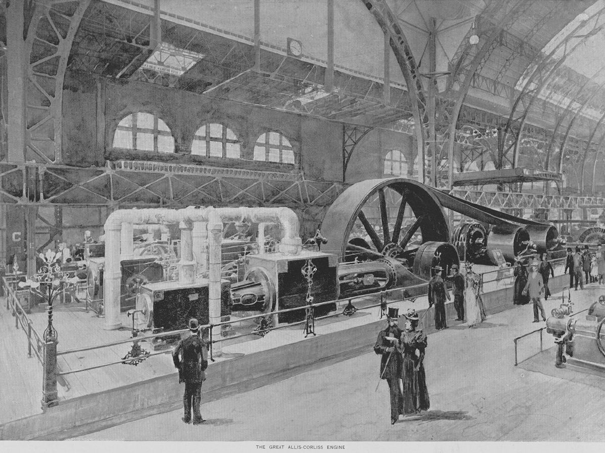
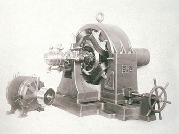
1893 E. P. Allis & Co., Quadruple Expansion Corliss Steam Engine - Image courtesy of vintagemachinery.org
[This engine and drive train held a number of world records at the time it was operating. In the above image only one of the two main drive belts are installed. You can see in the higher resolution illustration below, that two drive belts operated in tandem, one atop the other, driving two generator pulleys.]
Click for higher resolution image courtesy of the Paul V. Gavin Library
The second group consists of two generators, tandem-belted, driven by a 2,000 h.p. quadruple expansion Allis-Corliss engine, running at 60 revolutions per minute, standing on a foundation 57 feet 6 inches long, 28 feet wide and 13 feep 9 inches deep. The cylinders are 26, 40, 60, and 70 inches in diameter respectively, and have a stroke of 72 inches. The maximum capacity of this engine is 3,000 h.p. though it is rated at 1,000 less. It is provided with 36--16 Allis air pumps, driven by a Reynolds-Corliss cylinder. The three receivers are placed beneath the floor and nothing except the necessary piping is visible above, where it is so arranged that the two sides of the engine may be run as two distinct compound engines if desired. The fly wheel weighs about 50 tons and is 30 feet in diameter with a 76 inch face. It is made in 12 sections which in addition to being bolted together, have links sunk into their outer edges for additional security. The whole engine complete weights about 300 tons. The frame is of Mr. Edwin Reynolds' 1890 pattern and is wholly of cast iron. The receivers and cylinders are all steam-jacketed, and the latter are provided with 1/2 Reynolds-Corliss cut-offs; those on the two larger being regulated by hand and the others by governor.

A special Chapman throttle valve is used having a bypass for convenience when it is desired to admit a very little steam for any purpose, and the steam for the low pressure side, when the engines are run compound, is passed through a reducing valve. The cross head is also an unusually strong and solid affair. At one end it is made in one piece while the strap at the opposite end is secured with two gibs and a single key.

It may be added that the shaft is 17 feet long over all with a disc crank at the end. It is 21 inches in diameter in the center with 19 inch bearings, 32 inches long.

The remaining four generators are driven respectively by a McIntosh & Seymour, an Atlas Corliss, a Buckeye, and a Fraser and Chalmers' engine, each of 1,000 h.p.. Of these only the Buckeye is in a sufficiently advanced state of errection to obtain satisfactory data. This is a triple-expansion high-pressure engine, with a 20-inch high pressure and a 32-1/2 intermediate cylinder and two 36-inch low-pressure cylinders, with 48 inches stroke, running at a speed of 85 revolutions per minute. The shaft is 16 feet long with journals 13 inches in diameter and carries a five ton band wheel, 21 feet in diameter, with a 74 inch face. Wainwright surface condensers supplied by a Conover pump are used with this engine and are stowed away in a pit between the cylinders. There are also two combined Wainwright reheaters and receivers.
In addition to all these there are two 500 h.p. alternating-current generators direct-connected to Westinghouse compound engines, and the exciting currents are supplied by three "Kodak" generators delivering 300 amperes each at 250 volts, also direct-connected to a Westinghouse compound engine. Besides the lighting plant the Westinghouse Company are putting in a 500 h.p. slow speed multipolar, direct-current generator for the various motor circuits, direct-connected to an Allis-Corliss engine. This installation is also at present in a rather embryonic state.

The output of this enormous plant is distributed from a marble switchboard consisting of two distinct parts, i.e., the dynamo board and the feeder board.
The dynamo board is 32 feet long and 11 feet high, and consists of 18 panels, 13 distributing the output of the generators to the feeder board and the remaining five taking care of the exciting current. Of the 13 dynamo panels, 12 handle the 1,000 h.p. two-phase generators, while the 13th takes care of the two 500 h.p. machines. At the top of each panel are placed the Westinghouse voltmeters and ammeters. Below these come the switches, while at the bottom are the rheostats. The five panels of the exciter distribution board are arranged as follows: Four contain each an ammeter, an automatic circuit breaker, a switch, a voltmeter plug socket and a rheostat for a single exciter; the fifth panel contains the main ammeter and voltmeter.
The feeder board, 71 feet long and 9-1/2 feet high, distributes current from the dynamo board to 40 different circuits and has a separate panel for each. These panels contain the Stillwell regulators for feeder regulation, the switches, and the measuring instruments. The circuits pass through the subways, already fully described in The Electrical Engineer, to various buildings. A very attractive feature of the board is that for the high potential currents no points of contact appear on the outside, the switches being placed at the back of the board and having long insulated handles passing through openings to the front. Every panel of both boards has a pilot lamp at the top which adds greatly to the beauty of the whole, and the board itself, standing as it does high above the surrounding machinery and apparatus will be one of the most striking and conspicuous objects in the Palace of Mechanic Arts.
Note*: The 1893 World's Fair was fired with oil supplied by the Standard Oil Company, not coal. The firemen wore starched whites to show how much cleaner oil fired power was:
"Passing along the galleries of the boiler-houses, on a level with the floor of Machinery Hall and a few feet above the line of great furnaces, the visitor may notice that the stokers are attired in neat white uniforms, very unlike the begrimed and grease-stained garments characteristic of the craft. This is explained by the use of oil as fuel, conveyed in the Standard company's pipes from Whiting, Indiana, some forty miles distant. The oil is stored in iron tanks, enclosed in a massive brick vault in the south-eastern portion of the grounds, and with a total capacity of 112,000 gallons. This subterranean reservoir is in six compartments, each twice the size of the tanks, and thus is avoided or minimized the danger of explosion, should the grounds be swept by fire. Near by is the pumphouse, from which, at a distance of more than half a mile, the oil is delivered as needed at the stand-pipe near the boilerhouse. Each of the two pumps is furnished with a suction connection, by which, in case of accident at the boiler-house, the contents of the pipe may be returned to the storage tanks. The main lines of supply-pipes are enclosed in a heavy wooden box, covered by removable cast iron plates, with branches leading to the boilers which furnish power for the several groups of engines, presently to be described." -- The Book of the Fair, pg 310.

"The boilers are all of the water tube type, which in brief consists of a bank of tubes a few inches in diameter, and a dozen feet long, inclined upward, and connected with a large steam drum or reservoir. The tubes are expanded at either end, and the entire apparatus is filled with water up to about the middle of the drum. As the steam is generated by the flames beneath, it passes from each pair or battery of boilers into one common pipe, which delivers it in turn to the headers, or reservoirs, located under the gallery floor. The water is then drained from the headers, and returned to the boilers for further use by a separate system of pipes. To boilers of this pattern it is claimed that even an explosion causes but little damage, since the enormous power which they generate is distributed between eleven or twelve thousand tubes." -- The Book of the Fair, pg 310.
The largest boiler room in the world at the time it was built. Manufacturers competed to demonstrate the most efficient and effective systems, all boilers ran on standardized oil fuel.
For more on the engines at the 1893 World's Fair I highly recommend:
Steam Engines at the World’s Fair (Parts 1-2)
Note: The 1893 Fair's neoclassical architecture focused on symmetry, balance, and splendor. Buildings were covered with an artificial white stone known as staff, which was mixed and cast with what I suspect was copius amounts of white lead carbonate to look like carved white marble, thus giving it the nickname:
"The White City”
Related Article
Westinghouse Work at the Fair
The Electrical Engineer, August 16, 1893, Vol. XVI
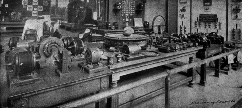
Mr. Tesla's Personal Exhibit at the World's Fair
Chapter XLII - The Martin Book
The Inventions, Researches, and Writings of
Nikola Tesla

Thomas Commerford Martin
Articles by Tesla
Tesla made public disclosures of means, methods, systems, and apparatus in various articles.
Tesla's Laboratory Power
Boiler, Steam Engine, Line-Shaft, Belts & Pulleys
To the Archive Page Discussion on Tesla's Technology